I/O tags - configuration dialog box
Editing of all objects in the process D2000 CNF is being performed in the configuration dialog box, a specific part of which is common for all editable objects and another part depends on the type of edited object.
The configuration dialog box of I/O tags consists of several parts (tabs) that contain similar parameters. The display of particular tabs depends on the category of particular I/O tag.
General properties
Groups
Process alarms
Destination
Address
Filter
Conversion
Output control
Default value
Polarity
Verification
General properties
Description
A text string describing the I/O tag. Maximum: 128 characters.
It is possible to use the Dictionary (press CTRL+L to open).
Status text
Defines a status text for the I/O tag. The status text allows redefining labels of individual I/O tag values.
Transformation palette
Selection of an index to transformation palette. See the topic Transformation palette.
Value type
I/O tag value type. Admissible types of values are listed in the following table.
| Label | I/O tag value type |
|---|---|
| Ai | Analog Input |
| Ao | Analog Output |
| Ci | Cardinal Input - integer input |
| Co | Cardinal Output - integer output |
| Di | Digital Input |
| Do | Digital Output |
| TiA | Time Input Absolute |
| ToA | Time Output Absolute |
| TiR | Time Input Relative |
| ToR | Time Output Relative |
| TxtI | Text Input |
| TxtO | Text Output |
| QI | Quaternary Input - quaternary input |
Technical units
Technical units of the I/O tag. Maximum: 12 characters. Possibility to use the Dictionary (press CTRL+L to open).
Limits
Technological limits may be defined for I/O tags of Ai, Ao, Ci, Co, TiR, and ToR types.
Process alarms

Timeout
Time delay (in seconds) for the evaluation of process alarm. Process alarm is raised, if a cause of raising the alarm is valid at least during this period.
Block Alarms
The Block Alarms checkbox disables the evaluation of process alarms.
Ignore Invalid
If checked, it allows removing invalid values when evaluating process alarms.
Example: Value change from S1 to S2 is executed as follows: S1 --> invalid --> S2.
If the parameter is checked, the alarm evaluation will be: S1 --> S2.
If the parameter is not checked, the alarm evaluation will be: S1 --> invalid --> S2.
Mask for NoAlarm
Selection of a Display mask, that will be used in process D2000 HI (the Alarm list window - the Event description column) after changing the status of one of the defined process alarms into the Normal state.
Individual items allowing to set parameters of process alarms are ordered in a table. The table contains the following columns:
- Alarm - the column contains all possible causes of raising process alarm for the object.
- State - the radio buttons allow selecting just one of the State, Transition, or None options. Enabled State option means, that the process alarm starts when the value of the I/O tag is at least for the period defined by the Timeout parameter, in the particular state (the name of a particular state is placed in the respective row, in the Alarm column - pa_ValueStateName).
- Transition - checked Transition option means that the process alarm starts when the I/O tag value passes to a particular state (the name of a particular state is placed in the respective row, in the Alarm column - pa_ValueStateName).
- None - process alarm is not evaluated when this option is enabled
- ACK - checked ACK option means that the process alarm must be acknowledged by an operator in process D2000 HI. "Transition" process alarm must be always acknowledged.
- Critical - this process alarm will have the critical flag.
- Monitor - the option will cause a particular change of the I/O tag value to be written into the log database as a spontaneous value change.
- Display mask - a selection of a display mask, that will be used in process D2000 HI (the Alarm list window - the Event description column) after changing the status of one of the defined process alarms to a particular state.
Raise SIGNAL
Raise SIGNAL parameter contains three checkboxes with the following function:
- the first checkbox - is placed below the State and Transition columns. When the option is enabled (checked), the system generates a signal, if any of the configured process alarms occur.
- the second checkbox - is placed below the Critical column. When the option is enabled (checked), the system generates the signal, if any of the configured critical process alarms occur.
- the third checkbox - is placed below the Monitor column. When the option is enabled (checked), the system will generate the signal, if any of the changes of defined process alarms are written into the log database.
Generating the signal means that the system tag Signal_Trigger is set to the TRUE value.
Destination
Destination column
It can contain the reference to a column of an object of the Structured variable type in the form ObjectName[0]^ColumnName. In such a case, the KOM process tries to copy the values of arrays with the start address which is configured in tab Address to the relevant column of the structured variable. There is no need to create individual I/O tags for each item of an array or for some other repeated address structure. Only selected communication protocols support this functionality. More additional information is mentioned in the description of a particular communication protocol.
The copying of values into the column of a structured variable is implemented only for input, the change of a particular value of a structured variable (e.g. in HI or via event) will not be transferred as output through the communication into the device.
The processing of values that are inserted into a structured variable is limited. The following processing is applied:
- Conversion
- Polarity
- Filter (except for the Oscillation, Value delay, and Alignment of value time)
- Limits
All parameters which are to be processed (e.g. limit setting) are applied according to the setting of the I/O tag where the destination column is configured (i.e. "master" I/O tag). The timestamps of the values inserted into the column of a structured variable are identical to the timestamp of a "master" I/O tag. The value of the "master" I/O tag and its behavior is normal, and it is not influenced byt the configuration of the destination column.
Address
Address
I/O tag address. The address type depends on the communication protocol of the station, which is the parent of a particular I/O tag. The address is stored in the configuration database in a text form. A specific communication protocol converts this address into a binary form. For internal communication protocols of the D2000 system, a protocol-dependent dialog box with the validity check of a specified address is used during the I/O tag address configuration. For external communication protocols (OEM Protocol 1 up to OEM Protocol 16) of the D2000 system, the address is entered directly in text form.
During the saving of the I/O tag configuration, the uniqueness of its address is tested. If the address of the I/O tag is not unique (within a parent station), the system will inform about the error. 
By choosing the option Yes, a new CNF dialog window opens. Only I/O tags with conflicting addresses sharing a common parent are displayed in this window. The user can (but does not have to) change the address of these I/O tags. 
Minute correction
A parameter is an integer number within the range of 0 to 59. If the time stamps of receiving values should be rounded to minutes, this value is important for rounding either up or down.
If the value is 0, it means the time correction is ignored. The timestamps of values that are limited by interval (0 - parameter) will be rounded down, i.e. to the minute in which they were received. Higher timestamps will be rounded up to the next minute.
Filter
Using the following group of parameters allows defining a filtering method of analog inputs and outputs - Ai, Ao, Ci, Co, TiR, ToR.
New time => new value
Values of I/O tags acquired from the communication, which have a new time and their values are not changed, will be represented as new values.
Limits by device
This option is available if the device and communication protocols allow detecting device limits. If the parameter is checked, then limits gained from communication with this device will be used.
None
The filtering of the I/O tag values is not enabled.
Value = New * K + Old * (1-K)
Weighed first-order filter.
- Value- value after filtering
- New - filtered value
- Old - previous value
- K - the weight of the new value - a real number from the interval (0.0 .. 1.0).
The Repeat Parameter: This parameter provides compatible weighted filter behavior for change-based and server protocols (IEC-60870-5-101, IEC-60870-5-104, Modbus Server, TG809, BACnet, OPC, OPC UA ...). If a positive value of the Repeat parameter is specified, it determines the period of repeated generation of the value received by the I/O tag - similar to when the same value is repeatedly retrieved for periodically polling protocols (e.g. Modbus Client). So, if a one-time change of the I/O tag value occurs, the weighted filter will gradually progress towards the target value by repeating this value.
Values out of limits are undefined
If a new value is less than Min or greater than Max, the system sets it as an undefined value.
Keep value always in limits
If a new value is less than Min value, the system will assign the Min value to this new value. If a new value is greater than Max value, the system will assign the Max value to this new value. This filter may be used to eliminate values, which technically may not break given limits (e.g. throttle stops), but the particular sensor (converter) may also generate values out of limits
Set value if out of limits
If a new value is less than Min value, the system will assign the SetMin value to this new value. If a new value is greater than Max value, the system will assign the SetMax value to this new value.
Ignore value if out of limits
If a new value is less than Min value or greater than Max value, it will be discarded.
Dead Band
Definition of the bandwidth (quantization level), within which changes are not sent into the system (they are filtered out).
Oscillation limits
I/O tag values, which are changed by defined Number times in defined time (Time spin button), will pass an object value state to Oscillate.
Value absorption
The system will assign the value from Value option to particular I/O tag, when its value belongs in <Value-Range ....Value+Range> interval.
Value delay
The system will assign a value (it is defined by selecting the particular button) to particular I/O tag only after it is unchanged during defined time [s].
Round value time to
Allows rounding the value time to the closest time with defined period (parameters Hours, Minutes and Seconds).
Conversion
Conversion to technical units may be defined for analogue and cardinal inputs and outputs - Ai, Ao, Ci, Co, TiR and ToR.
| Conversion type | Conversion formula |
|---|---|
| None | - |
| Linear | Output = A * Input + B |
| Polynomial | Output = A * Inputn *B x Input + C |
| Pt 100 | Output =  a = -5.802E-05 |
| Simatic S5Time | Conversion of the Siemens Simatic relative time structure. 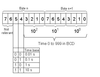 |
A, B, C, n - conversion constants
The above table shows the conversion performed when processing the value received from the device. An inverse conversion is performed when writing to the output I/O tag.
Therefore for I/O tags of output type (Ao, Co and ToR) it's possible to configure only the linear conversion, because only there exists unique inverse function used during value writing into particular device.
Output control
Enable mode change
The option will enable or disable mode change (from Manual mode into Auto mode and vice-versa) on the operator level in process D2000 HI.
- If the option is enabled, then a value must be entered into Start value input box and a control object must be defined - Control object input box. Valid mode is defined by means of Manual/Auto radio buttons. Mode may be changed in process D2000 HI and its changes are to be stored in the system database. Operator can change required value in Manual mode. Its change is also stored in the system database.
- If the option is disabled, then only one of Auto or Manual modes may be enabled. Operator's right to change required value is defined by means his/her access rights. Changing required value in process D2000 HI is allowed to an operator with Control access right level or higher.
Save mode changes
A mode change (from Manual mode to Auto mode and vice-versa) is stored into the configuration database.
Save start value changes
Each start value change performed through the control window in process D2000 HI is written into the configuration database.
Start value
Start value is saved in text form. Then it is converted to corresponding value type and is set as the value of the I/O tag. If it is not entered or the conversion has not been executed successfully, the initialization of output I/O tags' values is not executed.
Start value checkout 
The button Start value checkout () checks defined start value and reports failure if the conversion is not successful.
Control object
The value of this object is to be used as the value of the output I/O tag in the Auto mode.
Auto
Enabling the option causes the value of the output I/O tag to copy the value of control object.
Manual
Enabling the option causes the value of the I/O tag to use the value specified in the parameter Start value or operator sets it manually in process D2000 HI.
Output mode
I/O tag output mode.
- Value - I/O tag with own value acquired from the communication. Writing a new value of I/O tag into particular device is accompanied with the transient state. New value is confirmed after the communication verifies the writing.
- Command - Output I/O tag, that may not have own value (cannot acquire it by means of the communication with particular device). Writing a new value into the device do not pass through the transient state. Control windows in process D2000 HI also allow to write a value several times (e.g. enabled ON and OFF buttons at the same time - for value outputs, there is always enabled the button of the opposite value to the current one).
Execution timeout
The parameter defines the command execution timeout - writing a value of the I/O tag. If the value of the parameter is different from zero and writing an I/O tag value is not confirmed during the timeout, the writing is not consider as successful and there is occurred process alarm ErrorWriteCmd if defined (the item ErrorWriteCmd in the tab Process alarms).
Output time
The parameter Use D2000 Server time allows to use the time of the computer where process D2000 Server is running as the time for output I/O tag's value. Otherwise, the time acquired by the communication with the device, is used.
The parameter Maximum step size for a change allows to limit the maximum change of value for manual contol. This limitation has the character of a recommendation and a user is able to override it.
Default value
Default value allows to replace an I/O tag value acquired by process D2000 KOM by another one in some cases, (e.g. sensing device breakaway, failure of the communication with whole device). I/O tag value may be replaced by a value of other object (so-called control object), or adjusted manually by operator of process D2000 HI via the control window.
Use default value
Enables the use of default value. Default value for particular I/O tag is used automatically after starting process D2000 KOM.
Save changes of the default value mode
If the option Use default value is checked, then a change of the use of default value or disabling the default value from the control window in process D2000 HI is to be stored in the configuration database (it enables or disables the option Use default value).
Force default value on HardError
If the communication process evaluates an I/O tag value as unknown (acquired from the communication or failure of the communication with station), then the default value will be used. After the communication is recovered, the default value is cancelled and the I/O tag gets a value acquired from the communication. This change into the default value or cancelling the default value is not to be written into the configuration database (even if the option Save default value changes is enabled).
Allow switchover to default value in HI
Operator may switch an I/O value into the default value and vice-versa in process D2000 HI .
Enabled mode change
The option allows to enable or disable mode change (from Manual mode to Auto mode and vice-versa) on the operator level in process D2000 HI. If the option is enabled, a control object must be entered - Control object item.
Save default value changes
A change of the default value, adjusted manually in particular control window, is to be stored in the configuration database.
Default value
Default value is stored in text form. It is converted to required value type and then is used as the value of the I/O tag.
If it is not defined or conversion has failed, the initialization of the values of output I/O tag will not be executed (more info...).
Default value verification
Default value verification () button will verify entered default value and if is not valid, the system will display the report on it.
Control object
A value of this object will replace a value of the I/O tag in Auto mode.
Auto
Enabling the option, the I/O tag default value will be copied a value of the control object.
Manual
Enabling the option, the I/O tag default value will use a number in Default value input box or it will be adjusted manually by operator in process D2000 HI.
Polarity
Logical polarity of the I/O tag is adjusted for digital I/O tags - Di, Doout.
- Normal - an I/O tag value is not to be changed.
- Inverse - an I/O tag value is to be inverted.
Verification
The tab Verification allows to set confirmation for writing the output I/O tag (verified) using an input object (verifying). Verifying object can be an object of I/O tag, Switch or other types (e.g. Eval tag). For the I/O tag with enabled verification to be written successfully, it is not enough to send a value to the communication (and receiving the confirmation of successful writing from the partner station, if the communication protocol allows it), but a value of the verifying object must be received, that confirms the writing.
Verification is meaningful, if the D2000 system is part of a distributed control system (e.g. in energetics), where successful writing an I/O tag (e.g. setting the setpoint for the generator output) needn't mean that the real value was set changed to required level (the generator can be in the manual mode with the regulator disconnected, so the setpoint change of the regulator does not have any effect on the generator output). Only the new value of the measured generator output, that will be the same (with the Delta tolerance) as the value set, means that writing was successful.
When the verification is enabled, the following rules are valid :
- Writing a verified output I/O tag is successful, if a new value of the verifying object that confirms the value written will comes within the execution timeout (the Output control tab). Values of the verifying object, which do not meet the condition, will not cause any action (i.e. they do not cause unsuccessful writing).
- If the execution timeout is 0, there is waiting without limit.
- If the execution timeout expires, writing the output I/O tag is not considered to be successful and the alarm ErrorWriteCmd occurs, if it is configured.
- Within the execution timeout, several values of the verifying object may come. The values, which are not equal to the value written (with the Delta tolerance) do not cause the writing to be treated as unsuccessful, i.e. writing the I/O tag is unsuccessful when the execution timeout exceeds.
- If the value of the verifying object is equal with the written value (with the Delta tolerance) of the output I/O tag when writing, the writing is acting like the verification is not enabled, i.e. does not wait for new value of the verifying object, but writing is successful immediately after sending the value to the communication (and after confirmation, if the protocol supports it)
Table: evaluation of equation and validity of the tolerance parameter Delta for various type combinations of verifying object and verified output I/O tag.
| D - logical value I - integer value | R - real value Ta - absolute time Tr - relative time | Txt - text Q - quaternary value | |||||
| Verifying object Verified I/O tag | D | I | R | Ta | Tr | Txt | Q |
|---|---|---|---|---|---|---|---|
| Dout (logical) | equation | equation * | Delta | On/Off | |||
| Co (integer) | equation ** | Delta | Delta | Delta *** | |||
| Ao (real) | Delta ** | Delta | Delta | Delta *** | |||
| ToR (relative time) | Delta | Delta | |||||
| ToA (absolute time) | Delta | Delta | |||||
| TxtO (text) | equation | ||||||
Notes:
* - the value of 0 corresponds to the status B_False, the other values correspond to the status B_True
** - the values of 0, 1, 2 correspond to the states B_False, B_True, B_Oscillate of logical value
*** - the values 0, 1, 2, 3, 4 correspond to the states Q_Trans, Q_Off, Q_On, Q_Err, Q_Osc
Verifying object
An I/O tag (or Eval tag, Switch, ...), value of which is the reaction to writing the verified output I/O tag.
Delta
A number that determines the permitted deviation of the values of the verified output I/O tag and the verifying object. If the absolute value of the value difference is lower or equal to Delta, writing is successfully confirmed (Abs(Out-In)<Delta, details for various type combination are shown in the table above). For I/O tags of TxtO type (text output), the parameter is not used.
Absolute value
Delta is an absolute number.
Percent of range
Delta is a percent of range (the range is difference between the high and low limits of the verified object, i.e. HL - LL ). If the limits are defined dynamically and they are crossed, verification is evaluated according to the last valid Delta.