IEC 60870-5-104 communication protocol
Supported device types and versions
Communication partners
Communication line configuration
Communication station configuration
Tell commands
I/O tag configuration
Literature
Document revisions
Supported device types and versions
The protocol (known also as IEC 870-5-104 or IEC-104) allows reading and writing data, operating on the basis of TCP network communication. Implementation is, according to the IEC 60870-5-104 standard, as follows:
- Originator ASDU address is 1 byte, it is defined as the line number.
- ASDU address is 2 bytes, it is defined as the station address. ASDU addresses of all stations on one line must be different.
- Cause of transmission is 2 bytes (contains also Originator ASDU address).
- Information object address is 3 bytes, it is defined as an I/O tag address.
- The following ASDU types are implemented in the monitoring course (from controlled station to the D2000 system and also vice-versa in balanced mode):
Table 1
| ASDU type | I/O tag type |
|---|---|
| 1 - Single-point information | Di, Qi (On/Off), Ai, Ci |
| 2 - Single-point information with time tag | Di, Qi (On/Off), Ai, Ci |
| 3 - Double-point information | Qi, Ai, Ci |
| 4 - Double-point information with time tag | Qi, Ai, Ci |
| 5 - Step position information | Ci, Ai * |
| 6 - Step position information with time tag | Ci, Ai * |
| 7 - Bitstring of 32 bits | Ci, Ai |
| 8 - Bitstring of 32 bits with time tag | Ci, Ai |
| 9 - Measured value, normalized value | Ai |
| 10 - Measured value, normalized value with time tag | Ai |
| 11 - Measured value, scaled value | Ci, Ai |
| 12 - Measured value, scaled value with time tag | Ci, Ai |
| 13 - Measured value, short floating-point value | Ai |
| 14 - Measured value, short floating-point value with time tag | Ai |
| 15 - Integrated totals | Ci, Ai |
| 16 - Integrated totals with time tag | Ci, Ai |
| 17 - Event of protection equipment with time tag | Ci, Ai, TiR ** |
| 18 - Packed start events of protection equipment with time tag | Ci, Ai, TiR *** |
| 20 - Packed single-point information with status change detection | Ci, Ai |
| 21 - Measured value, normalized value without quality descriptor | Ai |
| 30 - Single-point information with time tag CP56Time2a | Di, Qi (On/Off), Ai, Ci |
| 31 - Double-point information with CP56Time2a tag | Qi, Ai, Ci |
| 32 - Step position information with CP56Time2a tag | Ci, Ai * |
| 33 - Bitstring of 32 bits with CP56Time2a tag | Ci, Ai |
| 34 - Measured value, normalized value with CP56Time2a tag | Ai |
| 35 - Measured value, scaled value with CP56Time2a tag | Ci, Ai |
| 36 - Measured value, short floating-point value with time tag CP56Time2a | Ai |
| 37 - Integrated totals with time tag CP56Time2a | Ci, Ai |
| 38 - Event of protection equipment with time tag CP56Time2a | Ci, Ai, TiR ** |
| 39 - Packed start events of protection equipment with time tag CP56Time2a | Ci, Ai, TiR *** |
| 40 - Packed output circuit information of protection equipment with time tag CP56Time2a | Ci, Ai, TiR *** |
| 241 - 64-bit floating-point value (Ipesoft & URAP implementation) | Ao |
| 243 - 64-bit floating-point value with time tag CP56Time2a (Ipesoft & URAP implementation) | Ao |
| 251 - Archive data values (Ipesoft's implementation) | none **** |
| 252 - D2000 Unival (Ipesoft's implementation) | all (except Qi) |
Note: Single bits of the byte, which informs us on quality (SIQ for ASDU 1,2,30; DIQ for ASDU 3,4,31; QDS for 5..14,20,32..36) are mapped into the FLA (0.bit), FLB (1.bit) ..FLH (7.bit) flags except the bits that are directly set by the value of the variable ( SCO bit 0, DCO and RCS bits 0-1). After receiving the answer (a positive/negative one), the FLA..FLH flags are set according to bits of "status" byte.
For example:
for ASDU 4: FLA=DPI bit 0, FLB=DPI bit 1, FLC=0, FLD=0, FLE=BL bit, FLF=SB bit, FLG=NT bit, FLH=IV bit.
for ASDU 16: FLA..FLE Sequence number bits 0..4, FLF=CY bit, FLG=CA bit, FLH=IV bit.
Moreover:
- if a bit is set to IV (Invalid), the value state will be Invalid
- if some of the bits are set to NT (Not topical), SB (Substituted), BL (Blocked), OV (Overflow), CA (Counter adjusted), CY (Counter overflow) for corresponding ASDU types, the value state will be Weak.
* - T-bit of the value of these ASDU types is in the FI flag, a number within -64 .. +63 is in a variable of Ci/Ai type.
** - ASDU 17 and 38: SEP byte is in the flags FLA (0.bit),FLB (1.bit)..FLH (7.bit), the following 2 bytes (CP16Time2a) are in a variable of Ci/Ai type as a positive number (0-60 000) or they are in a variable of TiR type as a relative time (0-60 seconds).
*** - ASDU 18, 39 and 40: SPE(ASDU 18,39) byte respectively OCI (ASDU 40) byte is in the flags FLI (0.bit),FLJ (1.bit) ..FLP (7.bit), QDP byte is in the flags FLA (0.bit),FLB (1.bit)...FLH (7.bit), the following 2 bytes (CP16Time2a) are in a variable of Ci/Ai type as a positive number (0-60 000) or they are in a variable of TiR type as a relative time.
The following ASDU types are implemented in the control course (from D2000 system to controlled station and also vice-versa in balanced mode):
Table 2
| ASDU type | I/O tag type |
|---|---|
| 45 - Single command | Dout |
| 46 - Double command | Dout |
| 47 - Regulating step command | Dout |
| 48 - Set point command, normalised value | Ao |
| 49 - Set point command, scaled value | Co |
| 50 - Set point command, short floating-point value | Ao |
| 51 - Bitstring of 32 bit | Co |
| 58 - Single command with time tag CP56Time2a | Dout |
| 59 - Double command with time tag CP56Time2a | Dout, Co |
| 60 - Regulating step command with time tag CP56Time2a | Dout |
| 61 - Set point command, normalised value with time tag CP56Time2a | Ao |
| 62 - Set point command, scaled value with time tag CP56Time2a | Co |
| 63 - Set point command, short floating-point value with time tag CP56Time2a | Ao |
| 64 - Bitstring of 32 bit with time tag CP56Time2a | Co |
| 250 - Archive data request command (Ipesoft's implementation) | none **** |
| 252 - D2000 Unival (Ipesoft's implementation) | all |
To set the bits of "status" byte (SCO for ASDU 45,58; DCO for ASDU 46,59; RCO for ASDU 47,60; QOS for ASDU 48..50,61..63), the flags FLA (0.bit),FLB (1.bit) ..FLH (7.bit) are used, except the bits, which are directly set by the variable value (SCO bit 0, DCO and RCS bits 0-1). Having received a response (positive/negative), the flags FLA..FLH are set according to the bits of the "status" byte.
When sending commands (ASDU 45-64), the value of 6 [Activation] is sent as a CauseOfTransmission. The expected response from the controlled station depends on the Command Confirm parameter. There are the following possibilities:
- writing is successful if the packet with RSN confirming the SSN packet with the write command
- writing is finished, if there is a response with CauseOfTransmission=7 [Activation Confirmation] and/or with 10 [Activation Termination]. Success/failure depends on the setting of the P/N bit in CauseOfTransmission.
**** - ASDU 250 can be used for communication with Ipesoft 870-5-104 Server. The command will ask for historical values (within specified interval) from the server, which will arrive as ASDU 251 (or newer ASDU 249 that use 64-bit values for improved precision, if the protocol parameter D2H64 is enabled on the server). The reading of the archive values can be executed by means of the GETOLDVAL command with the parameter containing the name of the I/O tag or station (in this case, the values of all I/O tag are read gradually, i.e. reading of the next tag starts after the reading of current tag is done).
Response for ASDU 250 is again ASDU 250 (with CauseOfTransmission=7) and with the return code:
- 0 - the successful start of reading the history
- 1 - the history for the required tag doesn't exist
- 2 - the history for the required tag is not available (the archive does not run)
Next (is the return code was 00) the ASDU 251 with archive data will be sent and the termination ASDU 250 with CauseOfTransmission=10.
Establishing a connection:
The D2000 KOM process is connecting to the TCP port and sends a StartDT Act U-frame, then a StartDT Con U-frame is expected as a reply.
For all the stations with a defined synchronization (see the article below), an ASDU type 103 [Clock synchronisation command] with CauseOfTransmission=6 [Activation] is sent, and a reply (depending on the Command Confirm parameter) is expected.
Then a sequence of 0 up to N I-frames with ASDU 100 [Interrogation Command] and ASDU 101 [Counter Interrogation Command] is sent, both with CauseOfTransmission=6 [Activation]. The I-frames are sent for each station with at least one input I/O tag (i.e. Ai, Di, Qi, Ci). As a response, there is expected (in any order):
- reception of frames with ASDU 100 [Interrogation Command] and with CauseOfTransmission=7 or 10 (depending on the Command Confirm parameter)
- reception of frames with ASDU 101 [Counter Interrogation Command] and with CauseOfTransmission=7 or 10 (depending on the Command Confirm parameter)
- reception of current values of all I/O tags.
The other side can also send frames with ASDU TypeIdentificator=100 and CauseOfTransmission=10 [Activation Termination]. However, the D2000 KOM process does not consider it to be an error if such no frames are received. The order of sending ASDU 100 and 101 as well as disabling their sending is defined by the Order of IC and Order of Counter IC parameters.
Clock synchronisation: Sending ASDU type 103 [Clock synchronisation command] is performed during initialization (after sending StartDT and before sending Interrogation Command). The synchronization is sent for the stations, with the Enable parameter checked in the Time parameters tab. ASDU type 103 is sent regularly with a defined period.
Forced disconnection: If all stations on the line are in the simulation mode or the communication is stopped for them, the line will be disconnected (communication socket will be closed). If the simulation is disabled for at least one station and the communication is not stopped for it (the Parameters tab of Station type object), the line will be connected again (and Interrogation Command and/or Counter Interrogation Command will be sent to the active station). After enabling communication for further stations, Interrogation Command and/or Counter Interrogation Command will be sent to these stations, see the next paragraph.
Forced sending of Interrogation Command and/or Counter Interrogation Command: If a station is in the simulation mode and the communication is not stopped for it (the Parameters tab of Station type object), the D2000 KOM process sends Interrogation Command and/or Counter Interrogation Command (see the parameters Order of IC, Order of Counter IC).
D2000 system also supports the balanced mode. In the mode, the task of controlled and control stations is changed. In this mode, the D2000 system receives commands and confirms them. The balanced mode may be used only when it is supported by partner station. An advantage is that D2000 system sends the current status of output I/O tags (defined as ASDU 1-40) as a reply to ASDU 100 [Interrogation Command] and 101 [Counter Interrogation Command] requests. It is still suitable to configure single-shot commands as ASDU 45 - 64; they are not repeated after re-establishing the connection.
As the protocol supports the balanced mode (partly it is a server), the rules of server protocols apply to it.
The output tags, which are configured as ASDU 1-40, do not go through the Transient status (i.e. they are considered as if in the configuration of I/O tag, Output control tab, the I/O tag output mode is set to Command). The writing is considered to be successful if there is the connection with server at the time of writing, otherwise the writing is unsuccessful.
Communication partners
- ABB MicroScada. Note: The value of the parameter Maximum message length in the ABB MicroScada settings must be changed from 253 similar to 230 (+/- a few bytes). Default value of the parameter causes rewriting the communication buffer and it is expressed by sending a corrupted message.
- PLC Bernecker & Rainer, protocol implementation: URAP-AUTOMATIZÁCIA s.r.o. (Ltd.)
- LFC terminals of Slovenské Elektrárne, a.s. (Inc.), protocol implementation: Energodata/ABB
- RS Unicon 4, UniControls
Communication line configuration
- Communication line category: TCP/IP-TCP or TCP/IP-TCP Redundant.
- TCP parameters - server parameters are mandatory:
- Host: string containing at most 80 characters – server name in form of INET (name or numerical address a.b.c.d). In case of redundant systems, multiple names/addresses separated by commas can be entered.
- Port: TCP port number (0..65535)
- Line number: is to be used as the Originator ASDU address (1 byte, 0-255)
Communication station configuration
- Communication protocol: IEC870-TCP.
- Station address a decimal number within the range of 0..65535 defines the ASDU address.
Note 1: After saving a station in process D2000 CNF, the process D2000 KOM automatically sends ASDU 100 and ASDU 101 (Interrogation and Counter Interrogation Commands) to this station, if enabled.
Note 2: The protocol supports sending long time stamps (CP56Time2a tag) in local time or UTC time with defined offset (see the parameter Use monotonic UTC time +).
Note 3: Starting with D2000 version 7.02.004 if a TCP Redundant line category is used, the FLC and FLD flags are used in the value of communication stations for indication of functionality of primary (FLC) and secondary (FLD) communication path. If these flags are set, the respective communication path is non-functional. For example, if the value of communication station is StON and FLC flag is set it means that only secondary communication path is functional.
For lower versions of D2000 only partial detection of a broken communication path is available when using the Strict Redundancy Connection Signalisation parameter.
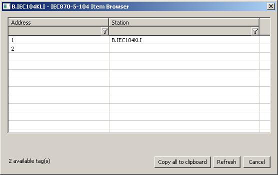
The Browse button opens a browsing dialogue for the station address. If the communication is functional, a dialogue with the ASDU addresses received so far is displayed. The Refresh button can be used to clear the list of received ASDU addresses.
Station protocol parameters
Table 3
| Full name | Meaning | Unit | Default value |
|---|---|---|---|
Asymmetric Redundancy Mode Periodicity | The parameter can be used for a TCP Redundant line with defined backup servers (see the parameters AS1, AP1, BS1, BP1 ..). The non-zero value of ARMP parameter means that if this number of ASDUs is received (after a successful reconnect), both connections are checked whether they're not going through the same network (IPs and ports defined in the line settings or ASx:APx and BSx:BPx). If they do, the connection to the standby server (see the Asymmetric Redundancy Mode Slave Detection parameter) will be closed and an attempt to establish a connection through another network will be made. If unsuccessful, the next IP address will be tried (i.e. Alternate Server 1, Alternate Server 2, line IP, Alternate Server 1, etc). Note: When the parameter Asymmetric Redundancy Mode Periodicity is enabled, the second connection is established to "B-Alternate Server 1":"B-Alternate Port 1" and not to the IP address and port defined for the line after running the D2000 KOM process (so that it wouldn't be immediately closed). | - | 0 |
Asymmetric Redundancy Mode Slave Detection | The detection method of standby server for Asymmetric Redundancy Mode Periodicity:
| - | 0 |
Alternate Server 1/ Alternate Port 1/ Alternate Server 2/ Alternate Port 2/ | Extension for redundant systems: besides the IP address defined in the configuration of the Line, it is possible to define 2 alternative IP addresses. In case of a connection failure, the D2000 KOM process is attempting to connect to the next address in the list. Note 1: All IP addresses and ports must be defined gradually for one station (i.e. at first "Alternate Server 1", "Alternate Port 1" and then "Alternate Server 2", "Alternate Port 2"). Note 2: These parameters are obsolete since it's possible to define several IP addresses in the configuration of the line (separated by comma or semicolon, e.g. 10.0.0.1;10.0.0.2). | - | - |
B-Alternate Server 1/ B-Alternate Port 1/ B-Alternate Server 2/ B-Alternate Port 2/ | Can be used when the protocol IEC 870-5-104 is configured for a TCP redundant line. The meaning of the parameters is the same as for the primary connection, but they are valid for the backup connection. Note 1: All IP addresses must be defined stepwise for one station (i.e. at first "Alternate Server 1", "Alternate Port 1" and then "Alternate Server 2", "Alternate Port 2"). Note 2: These parameters are obsolete since it's possible to define several IP addresses in the configuration of the line (separated by comma or semicolon, e.g. 10.0.0.1;10.0.0.2). | - | - |
Command Confirm | Confirmation of control ASDU. If Command Confirm=0, the D2000 KOM process is not waiting for confirmation of control ASDU from the partner station using a reply ASDU with a different CauseOfTransmission. ASDU is considered to be confirmed when a packet containing the corresponding ReceiveSequenceNumber is received. If Command Confirm=1, the D2000 KOM process is waiting for confirmation with CauseOfTransmission=7 (Activation Confirmation). If Command Confirm=2, the D2000 KOM process is waiting for confirmation with CauseOfTransmission=10 (Activation Termination). If Command Confirm=3, the D2000 KOM process waiting for confirmation with CauseOfTransmission=7 or 10 (if both of them are received, only the first of them is taken into account). Having received corresponding confirmation means that writing is finished (the Transient attribute of written value is cleared and the "Wait Timeout Tn" timeout stops elapsing). If a confirmation with a CauseOfTransmission different from the one the D2000 KOM process expects, is received, it will be ignored. Writing is successful if the received ASDU contains the P/N bit set to 0. Otherwise, writing is unsuccessful. Value from received ASDU is written back into a particular I/O tag and is sent to the system. E.g. if an ASDU of type 50 (short floating point) with the value of 1200.0 is sent and the partner station sends an ASDU of type 50 as a reply, P/N bit=0, the value of 999.0 (e.g. due to physical limitations of the given parameter) as a response, then the value will be sent to the D2000 system by the D2000 KOM process. | - | 1 |
These parameters are intended for the configuration of a communication station for communication between two D2000 systems using ASDU 252 - D2000 Unival (Ipesoft's implementation). more ... | |||
Debug Input | A mask for debug levels of input data. The meaning of bits is as follows:
| - | 0 |
Debug Output | A mask for debug levels of output data. The meaning of bits is as follows:
| - | 0 |
End of initialization | Extension for ABB MicroScada: If End of initialization=1, having received ASDU 70 (End of initialisation) resends Interrogation Command and/or Counter Interrogation Command. | - | 0 |
Force Master Time | If Force Master Time=True, then the D2000 KOM process will accept ASDU 103 (Clock synchronisation command) with CauseOfTransmission=6 [Activation] or 3 [Spontaneous] from the server and saves the time difference between the server's time and its time. If CauseOfTransmission=6, it replies with CauseOfTransmission=7 [Activation Confirmation]. Then time of all values, which are received with timestamps, is decreased by this difference, i.e. a correction to the time of D2000 is made. The parameter allows solving the problem when some values from the server are received with the timestamps and others without timestamps and times from D2000 and server differ. In this case, without parameter Force Master Time=True the values received without timestamps are tagged by D2000 time and the values with the timestamps are tagged by the server time. With parameter Force Master Time=True the time, sent by server, is corrected to D2000 time using the time difference, which is computed from the received ASDU 103 (Clock synchronisation command). | - | False |
Force Slave Time | Extension for ABB MicroScada: If Force Slave Time=True, then the D2000 KOM process will accept ASDU 103 (Clock synchronisation command) with CauseOfTransmission=6 [Activation] or 3 [Spontaneous] from the server and saves the time difference between server time and its time. If CauseOfTransmission=6, it replies with CauseOfTransmission=7 [Activation Confirmation]. Then all values, which are received with no timestamps, are to be marked by the current time plus time difference (if the station is not configured to use the communication computer time). The parameter Force Slave Time allows to solve the problem, that receiving ASDU 100 or 101, the ABB MicroScada sends "interrogated" values without timestamps, however, during the communication, the values are sent with the timestamps - problems can occur, when the times of the MicroScada and the D2000 system are not synchronized. | - | False |
GI Send New | If GI Send New=True, then the D2000 KOM process, after receiving the General Interrogation command, sends also values with more recent times than the time when the command was received. The value of the GI Send New parameter must be True to send values with future times as a reply to the General Interrogation command. | - | False |
Ignore Control Field 3 bit 0 | Determines behavior, when ASDU contains Control Field with the lowest bit (1) of the 3rd-byte set.
| - | False |
Ignore Invalids on Interrogation | Balanced mode: if this parameter is set on a station, the D2000 KOM process will not send as a reply for ASDU 100 and 101 (Interrogation / Counter interrogation command) values of I/O tags which are Invalid or Unknown. The parameter can be used e.g. when controlling if sending Invalid values causes a breakdown of control. | - | False |
Ignore Tests | Determines behavior, when ASDU contains bit 8 (test) set in CauseOfTransmission.
| - | 0 |
Ignore Unknown Addresses | If Ignore Unknown Addresses=TRUE, the D2000 KOM process will not show an error on its console or write it into log files in case that incoming value has the address not matching any of the addresses of I/O tags defined in the D2000 system. | - | False |
Implicit Interrogation | Balanced mode: After connecting to the IEC104 server, the D2000 KOM process sends the values of all variables without waiting for ASDU 100 or 101 [Interrogation/Counter Interrogation Command] requests. | - | False |
Interrogation Covers Counter Interrogation | Balanced mode: As a reply to Interrogation, also values of I/O tags configured as ASDU 15, 16, 37 (Integrated Totals) are sent. (They are normally requested by ASDU 101 [Counter Interrogation].) | - | False |
Interrogation WithOut Timestamps | If Interrogation WithOut Timestamps=True, then values sent as a response to ASDU 100 [Interrogation Command] in balanced mode will be sent as ASDUs without timestamps. For example instead of ASDU 2 (Single-point information with time tag) or ASDU 30 (Single-point information with time tag CP56Time2a) ASDU 1 (Single-point information) will be sent. This behavior is suitable in the situation when the values have been invalidated as a result of communication error and after the communication is reestablished the values come with old timestamps which causes problems in the archive (if the values change only rarely, calculated archives depending on them will be also invalid till a new value arrives). At the same time, this behavior is strictly according to the IEC standard, which says that the response to Interrogation should not use ASDUs with time stamps. | - | False |
K | Sending window size i.e. number of I-frames sent by the D2000 KOM process without receiving a confirmation (S-frame or I-frame). According to the standard, the default value is 12. | - | 12 |
LFC History | The parameter may be used to read historical values for communication with LFC terminals or other devices that support ASDU 250 defined by Ipesoft. Unlike the primary use of ASDU 250, the LFC terminal can only transmit one value for interval begin time, while the end time is ignored. The value will not be received as ASDU 251 but as one of the standard ASDU with a timestamp. Moreover, the values (with the same timestamp) of other tags may be received along with the value of the required tag. LFC terminal does not send ASDU 250 (with CauseOfTransmission=7, 10) as part of the response to ASDU 250 and the D2000 KOM process considers the reading done as soon as it gets the value of the required I/O tag. If the value is not received within the time defined by the Wait Timeout T1 parameter, the reading of historical value is considered unsuccessful, however, the connection to the LFC terminal is not closed. If the values of other I/O tags are received along with the value of the required I/O tag, they must be received before the value of the required tag is received, otherwise, they are not considered as historical values (because reading is considered to be done after the value of required I/O tag is received). If the parameter is not defined or LFC History=0, reading of historical data is defined by Ipesoft (D2000 IEC104 Server partner is assumed). If LFC History=1, then the value is considered to be historical (it will go to the archive but not to the I/O tag, etc.) if its timestamp belongs to the time interval specified by the GETOLDVAL action (and is received as ASDU 250). If LFC History=2 then the behavior is as for LFC History=1 except if the timestamp of the received value is newer than the timestamp of the current value of the I/O tag, the received value will be sent into the D2000 Server process as a new one and not as a historical one. Note: When reading historical data of the LFC terminal, theGETOLDVAL action may not contain station name (thestatIdent parameter) but the I/O tag name. If the action contains a station name, ASDU 250 will be sent for one I/O tag only. | - | 0 |
Maximum Time Difference | Maximum acceptable time difference (in hours) between the time of received data and the time of the D2000 KOM process. If the partner station sends a value with a timestamp older or later than MDT hours, the value will be ignored and an error log will be written into the line's trace file. If the Maximum Time Difference parameter is a negative value (e.g. Maximum Time Difference=-5), its absolute value is used and the system alarm SystemError will be generated as well. If the parameter's value is zero, the time difference will not be checked. | hrs | 0 |
No Flags | If the parameter is True, then the status byte of incoming ASDUs is ignored and not saved into the FA...FH flags. Flags of output I/O tags are also ignored and they are not written to the status byte. | - | False |
Order of IC | Order of sending ASDU 100 [Interrogation Command] during connection initialization. If OIC<OCIC, ASDU 100 will be sent before ASDU 101. If OIC=0, ASDU 100 will not be sent. The parameter can be set extra for each station. | - | 1 |
Order of Counter IC | Order of sending ASDU 101 [Counter Interrogation Command] during connection initialization. If Order of IC < Order of Counter IC, ASDU 101 will be sent before ASDU 100. If Order of IC=0, ASDU 101 will not be sent. The parameter can be set extra for each station. | - | 2 |
Ping Count | Number of repetitions, after which the IP address not responding to ping is known as non-functional. See the parameter Ping TimeOut. | - | 3 |
Ping TimeOut | If the parameter is other than zero, then defines the timeout (in milliseconds) of server response for ping (ICMP echo) packet. In the background, the process D2000 KOM sends ping packets to all defined IPs - Line IP address and Alternate Server 1, Alternate Server 2, B-Alternate Server 1, B-Alternate Server 2. If some of the addresses does not response for Ping Count-times, it is designated as non-functional. If the line is connected to this IP address, the connection is terminated. New connection is established just to a functional IP address. If the parameter Ping TimeOut=0, sending ping packet to IP addresses is disabled. | ms | 0 |
Post start delay | A delay between receiving StartDT Con response and sending Interrogation Command and/or Counter Interrogation Command in the initialisation phase. | ms | 0 |
Pre Reconnect Delay | A delay before connecting and reconnecting (after starting the process D2000 KOM and after communication break-up). | ms | 0 |
Send sequence number | Initial Send sequence number. According to the standard, having established the connection the Send sequence number is set to 0, other than zero could be appropriate e.g. for testing. | - | 0 |
Smart Redundancy Minimum | Number of values that must be identical in the Smart Redundancy Minimum mode to consider the connections synchronized. The following parameters are taken into account:
| - | 5 |
Smart Redundancy Mode | Can be used for TCP Redundant line as alternative to Ignore Tests=1 or Ignore Control Field 3 bit 0=1. The process D2000 KOM assumes that the identical values go via the both connection of the TCP Redundant line in the same order. The process D2000 KOM is attempting to synchronize the connections. If the D2000 KOM process receives a number of identical values defined by the parameter Smart Redundancy Minimum, data are synchronized. After synchronisation is done, the value that comes earlier is taken into account, the same value via the other connection is ignored. When the TCP connection is broken or two different values comes, the synchronisation is broken. Compared to detection hot/standby partner by means of Ignore Tests/Ignore Control Field 3 bit 0, an advantage is that after communication failure with the hot server, there is no data loss, because the communication is still working with the standby partner and attempting to recover the connection with the hot server. Having recovered the connection (if the second connection is working), there are ignored the values which are acquired by the command General Interrogation. | - | False |
Standby Keep Open | If True, after changing the status of process D2000 Server (the process D2000 KOM is connected to) from Hot into Standby state (redundant system), connection with the server will not be closed. | - | False |
Standby Set Control Field | If TRUE, after changing the status of process D2000 Server (the process D2000 KOM is connected to) from Hot to Standby state (in the redundant system), the lowest bit of the 3rd Control Field byte of information APDUs (APDU containing data or commands) will be set to 1 instead of the standard value of 0. The behaviour does not strictly follow the standard and we recommend you to use the parameter Standby Set Test Bit instead of this parameter if it is possible. | - | False |
Standby Set Test Bit | If True, the Cause Of Transmission will have a Test bit set if the process D2000 KOM is connected to Standby server (redundant system) or is a passive instance. | - | False |
Standby Write Values | If True, after changing the status of process D2000 Server (the process D2000 KOM is connected to) from Hot into Standby state (redundant system), there will be sent new values. | - | False |
Station Communication Error | Number of unsuccessful connection attempts after the communication failure after which the station status is changed to St_CommErr. For redundant lines, the communication must be either failed on both TCP connections or only a TCP connection to standby-server must be established (see the parameters Ignore Control Field 3 bit 0 and Ignore Tests), i.e. data from the server are ignored. | - | 2 |
Station Hard Error | The status of all stations on line is changed into the state St_HardErr if the following conditions are met:
| - | 5 |
Stop Data Confirm Ignored | Workaround due to MetsoDNA server error: after connecting to IEC870-5-104 server from the firm Metso, the server sends a U-frame STOPDTcon (thereby confirms interruption in sending data). If the parameter Stop Data Confirm Ignored is True, this frame will be ignored and the communication will continue. Without the parameter Stop Data Confirm Ignored, the connection will be aborted. | - | False |
Strict Redundancy Connection Signalisation | Determines behaviour, when the protocol is used for TCP Redundant line
| - | False |
Tcp Keep Init | The parameter is implemented for use on OpenVMS platforms only. If it is other than zero, then defines the timeout (in seconds) for opening a new connection to server. For OpenVMS, the default value is 75 seconds, for Windows it is 20 seconds. When timeout expires, connect procedure returns error. | - | 0 |
Tcp No Delay | Setting Tcp No Delay parameter causes low level socket option TCP_NODELAY being set, thus turning off default packet coalesce feature. | - | False |
W | Number of received I-frames, after which the process D2000 KOM sends a S-frame confirmation. According to the standard, the default value is 8. The relation W < K must be true, the standard recommends W = 2/3 * K. | - | 8 |
Wait Timeout T1 | Timeout for receiving the confirmation of a sent I-frame (either confirmation within the I-frame or the S-frame itself) or a U-frame. If the process D2000 KOM does not get the confirmation in the time Wait Timeout T1, it closes the TCP connection. According to the standard, the Wait Timeout T1 default value is 15000 ms. | ms | 15 000 |
Wait Timeout T2 | Timeout for sending the confirmation of a received I-frame. Wait Timeout T2 < Wait Timeout T2. If other I-frame (which confirms the received I-frame) is not sent in the time Wait Timeout T2 since the I-frame was received, so the process D2000 KOM sends a S-frame confirming the received I-frame to the partner. According to the standard, the Wait Timeout T2 default value is 10000 ms. | ms | 10 000 |
Wait Timeout T3 | Timeout for sending test frames (U-frame TEST ACT). If no data are sent in any direction for a long time, an U-frame TEST ACT will be sent to the process D2000 KOM after expiration of the Wait Timeout T3 time and there is expected (in the Wait Timeout T1 time after sending) receiving a U-frame TEST CON. If the Wait Timeout T3 on the partner side is set to a lower value, it sends the test frames and the process D2000 KOM reply them. According to the standard, the Wait Timeout T2 default value is 20000 ms. Setting the value to 0 disables sending test frames. | ms | 20 000 |
Wait Timeout No answer | Timeout for receiving the confirmation of a sent value. Receiving e.g. S-frame with RSN (Receive Sequence Number) confirming, that the other party received previous I-frame doesn't mean, that the I-frame was processed. In the Wait Timeout Tn, the process D2000 KOM waits for receiving the response (e.g. after sending ASDU with TypeIdentificator=45 [Single Command] with CauseOfTransmission=6 [Activation] there is expected receiving Single Command with CauseOfTransmission=7 [Activation Confirmation]. After the expiration of the Wait Timeout Tn, the process D2000 KOM closes the TCP connection. | ms | 60 000 |
Defined parameters, except for Order of IC, Order of Counter IC and Force Slave Time, are valid for the entire line - i.e. it is enough to define them for one station on the line.
Tell commands
Table 4
| Command | Syntax | Description |
| STCOMMAND | STCOMMAND StationName DISCONNECT | Tell command closes immediately the active TCP connections of the communication line (a parent of "StationName"). Then the connection is restarted and re-connected. |
| STWATCH | STWATCH StationName | Tell command sends Interrogation Command and/or Counter Interrogation Command to the station (depending on station parameters). |
Examples of configurations
Example 1: Client communicating with the server SrvA within redundant network.
Server settings
| Client settings
|
If a communication segment drops out (e.g. IPA1 failure) the client establishes connection with the server SrvA using the address IPA2.
Example 2: Client communicating with the redundant servers SrvA, SrvB.
Servers' settings
| Client settings
|
The client communicates both with the hot server and with the standby server, connection with the standby server continues to be open, but new values are send by the hot server.
Note: If symbolic myName is used, it should be defined in hosts file of 1-st server as IPA and in hosts file of 2-nd server as IPB.
Example 3: Client communicating with the redundant servers SrvA, SrvB within redundant network.
Servers' settings
| Client settings
|
The client communicates with both the servers. If one network segment drops out (e.g. IPA1 failure), the client establishes connection with the server SrvA using the address IPA2.
Example 4: The redundant clients ClientC, ClientD communicating with the redundant servers SrvA, SrvBwithin redundant network.
Servers' settings
| Clients' settings
|
The clients communicate with both the servers. If one network segment drops out (e.g. IPA1 failure), the clients establish connection with the server SrvA using the address IPA2. After switching the hot/standby statuses of the clients ClientC and ClientD, they keep communicating with the servers, but the active client only sends commands. New values are sent by the active server.
I/O tag configuration
Possible I/O tag types: Ai, Ao, Ci, Co, Di, Dout, Qi
- I/O tag address is mapped on Information object address, i.e. it has 3 bytes and must within the range of 0..16777215.
- Input tags must be particular types (Ai, Ci, Di, Qi) for received ASDU, see the table 1 and also the table 2 in the balanced mode.
- For particular type of output tag (Ao, Dout, Co) it is necessary to set a ASDU type, that has to be used, see the table 2.
- Archive for providing historical values: if client asks for historical values through ASDU 250, the server sends:
- the values of the historical value specified by this input entry field,
- if the input entry field is not filled, then the values of the historical value that archives the I/O tag,
- if given historical value does not exist, then the values of the I/O tag that archives the control object of given I/O tag,
- if the control object does not exist (or the archive is not available), the server returns an error.
Literature
-
Document revisions
- Ver. 1.0 – July 30th 2003
- Ver. 1.1 – November 19th 2003: extension of supported ASDU, new parameters
- Ver. 1.2 – March 20th 2004: added ASDU for reading archive data
- Ver. 1.3 – June 20th 2004: extension - redundancy support
- Ver. 1.4 – December 1st 2004: extension - support of balanced mode
- Ver. 1.5 - December 12th, 2012 - updating, tell commands
Related pages:
IEC 870-5-104 communication protocol
Supported device types and versions
Communication partners
Communication line configuration
Communication station configuration
Tell commands
I/O tag configuration
Literature
Document revisions
Supported device types and versions
The protocol allows reading and writing data, operating on the basis of TCP network communication. Implementation is, according to the IEC870-5-104 standard, as follows:
- Originator ASDU address is 1 byte, it is defined as the line number.
- ASDU address is 2 bytes, it is defines as the station address. ASDU addresses of all stations on one line must be different.
- Cause of transmission is 2 bytes (contains also Originator ASDU address).
- Information object address is 3 bytes, it is defined as an I/O tag address.
- The following ASDU types are implemented in the monitoring course (from controlled station to the D2000 system and also vice-versa in balanced mode):
Table 1
| ASDU type | I/O tag type |
|---|---|
| 1 - Single-point information | Di, Qi (On/Off), Ai, Ci |
| 2 - Single-point information with time tag | Di, Qi (On/Off), Ai, Ci |
| 3 - Double-point information | Qi, Ai, Ci |
| 4 - Double-point information with time tag | Qi, Ai, Ci |
| 5 - Step position information | Ci, Ai * |
| 6 - Step position information with time tag | Ci, Ai * |
| 7 - Bitstring of 32 bits | Ci, Ai |
| 8 - Bitstring of 32 bits with time tag | Ci, Ai |
| 9 - Measured value, normalized value | Ai |
| 10 - Measured value, normalized value with time tag | Ai |
| 11 - Measured value, scaled value | Ci, Ai |
| 12 - Measured value, scaled value with time tag | Ci, Ai |
| 13 - Measured value, short floating point value | Ai |
| 14 - Measured value, short floating point value with time tag | Ai |
| 15 - Integrated totals | Ci, Ai |
| 16 - Integrated totals with time tag | Ci, Ai |
| 17 - Event of protection equipment with time tag | Ci, Ai, TiR ** |
| 18 - Packed start events of protection equipment with time tag | Ci, Ai, TiR *** |
| 20 - Packed single-point information with status change detection | Ci, Ai |
| 21 - Measured value, normalized value without quality descriptor | Ai |
| 30 - Single-point information with time tag CP56Time2a | Di, Qi (On/Off), Ai, Ci |
| 31 - Double-point information with CP56Time2a tag | Qi, Ai, Ci |
| 32 - Step position information with CP56Time2a tag | Ci, Ai * |
| 33 - Bitstring of 32 bits with CP56Time2a tag | Ci, Ai |
| 34 - Measured value, normalized value with CP56Time2a tag | Ai |
| 35 - Measured value, scaled value with CP56Time2a tag | Ci, Ai |
| 36 - Measured value, short floating point value with time tag CP56Time2a | Ai |
| 37 - Integrated totals with time tag CP56Time2a | Ci, Ai |
| 38 - Event of protection equipment with time tag CP56Time2a | Ci, Ai, TiR ** |
| 39 - Packed start events of protection equipment with time tag CP56Time2a | Ci, Ai, TiR *** |
| 40 - Packed output circuit information of protection equipment with time tag CP56Time2a | Ci, Ai, TiR *** |
| 241 - 64-bit floating point value (Ipesoft & URAP implementation) | Ao |
| 243 - 64-bit floating point value with time tag CP56Time2a (Ipesoft & URAP implementation) | Ao |
| 251 - Archive data values (Ipesoft's implementation) | none **** |
| 252 - D2000 Unival (Ipesoft's implementation) | all (except Qi) |
Note: Single bits of the byte, which informs us on quality (SIQ for ASDU 1,2,30; DIQ for ASDU 3,4,31; QDS for 5..14,20,32..36) are mapped into the flags FLA (0.bit), FLB (1.bit) ..FLH (7.bit) except the bits that are directly set by the value of variable ( SCO bit 0, DCO and RCS bity 0-1). After receiving the answer (a positive /negative one), the flags FLA..FLH are set according to bits of "status" byte.
For example:
for ASDU 4: FLA=DPI bit 0, FLB=DPI bit 1, FLC=0, FLD=0, FLE=BL bit, FLF=SB bit, FLG=NT bit, FLH=IV bit.
for ASDU 16: FLA..FLE Sequence number bity 0..4, FLF=CY bit, FLG=CA bit, FLH=IV bit.
Moreover:
- if a bit is set to IV (Invalid), the value state will be Invalid
- if some of the bits are set to NT (Not topical), SB (Substituted), BL (Blocked), OV (Overflow), CA (Counter adjusted), CY (Counter overflow) for corresponding ASDU types, the value state will be Weak.
* - T-bit of the value of these ASDU types is in the FI flag, a number within -64 .. +63 is in a variable of Ci/Ai type.
** - ASDU 17 and 38: SEP byte is in the flags FLA (0.bit),FLB (1.bit)..FLH (7.bit), the following 2 bytes (CP16Time2a) are in a variable of Ci/Ai type as a positive number (0-60 000) or they are in a variable of TiR type as a relative time (0-60 seconds).
*** - ASDU 18, 39 and 40: SPE(ASDU 18,39) byte respectively OCI (ASDU 40) byte is in the flags FLI (0.bit),FLJ (1.bit) ..FLP (7.bit), QDP byte is in the flags FLA (0.bit),FLB (1.bit)...FLH (7.bit), the following 2 bytes (CP16Time2a) are in a variable of Ci/Ai type as a positive number (0-60 000) or they are in a variable of TiR type as a relative time.
The following ASDU types are implemented in the control course (from D2000 system to controlled station and also vice-versa in balanced mode):
Table 2
| ASDU type | I/O tag type |
|---|---|
| 45 - Single command | Dout |
| 46 - Double command | Dout |
| 47 - Regulating step command | Dout |
| 48 - Set point command, normalised value | Ao |
| 49 - Set point command, scaled value | Co |
| 50 - Set point command, short floating point value | Ao |
| 51 - Bitstring of 32 bit | Co |
| 58 - Single command with time tag CP56Time2a | Dout |
| 59 - Double command with time tag CP56Time2a | Dout, Co |
| 60 - Regulating step command with time tag CP56Time2a | Dout |
| 61 - Set point command, normalised value with time tag CP56Time2a | Ao |
| 62 - Set point command, scaled value with time tag CP56Time2a | Co |
| 63 - Set point command, short floating point value with time tag CP56Time2a | Ao |
| 64 - Bitstring of 32 bit with time tag CP56Time2a | Co |
| 250 - Archive data request command (Ipesoft's implementation) | none **** |
| 252 - D2000 Unival (Ipesoft's implementation) | all |
To set the bits of the status byte (SCO for ASDU 45,58; DCO for ASDU 46,59; RCO for ASDU 47,60; QOS for ASDU 48..50,61..63), there are used the flags FLA (0.bit),FLB (1.bit) ..FLH (7.bit) except the bits, which are directly set by the variable value ( SCO bit 0, DCO and RCS bits 0-1). Having received a response (positive/negative), the flags FLA..FLH are set according to the bits of the "status" byte.
When sending commands (ASDU 45-64), the value of 6 [Activation] is sent as CauseOfTransmission. Expecting a response from the controlled station depends on the parameter Command Confirm. There are the following possibilities:
- writing is successful if the packet with RSN confirming the SSN packet with the log
- writing is finished, if there is a response with CauseOfTransmission=7 [Activation Confirmation] and/or with 10 [Activation Termination]. Success/Unsuccess depends on the setting of the P/N bit in CauseOfTransmission.
**** - ASDU 250 can be used for communication with Ipesoft 870-5-104 Server. The command will ask for historical values (within any interval) from the server, which are returned as ASDU 251 (or newer ASDU 249 that use 64-bit values for improved precision, if the protocol parameter D2H64 is enabled on the server). The reading of the archive values can be executed by means of the TELL command GETOLDVAL with the parameter containing the name of the I/O tag or station (in this case, the values of all I/O tag are read in successive steps, i.e. reading of next tag starts after the termination of currently read tag).
Response for ASDU 250 is again ASDU 250 (with CauseOfTransmission=7) and with the return code:
- 0 - the successful start of reading the history
- 1 - the history for the required tag doesn't exist
- 2 - the history for the required tag is not available (the archive does not run)
Further follows (is the return code was 00) ASDU 251 with archive data and the termination ASDU 250 with CauseOfTransmission=10.
Establishing a connection:
The D2000 KOM process is connecting to the specified TCP port and sends StartDT Act U-frame, StartDT Con is expected as a reply.
For all the stations with a defined synchronization (see the article below), ASDU type 103 [Clock synchronisation command] is sent with CauseOfTransmission=6 [Activation], and a reply is expected (depending on the Command Confirm parameter).
Then a sequence of 0 up to N I-frames with ASDU 100 [Interrogation Command] and ASDU 101 [Counter Interrogation Command] is sent, both with CauseOfTransmission=6 [Activation]. The I-frames are sent for each station with at least one input I/O tag (i.e. Ai, Di, Qi, Ci). An expected response is (in any order):
- reception of frames with ASDU 100 [Interrogation Command] and with CauseOfTransmission=7 or 10 (depends on Command Confirm)
- reception of frames with ASDU 101 [Counter Interrogation Command] and with CauseOfTransmission=7 or 10 (depends on Command Confirm)
- reception of current values of all I/O tags.
The other party can also send frames with ASDU TypeIdentificator=100 and CauseOfTransmission=10 [Activation Termination], but the D2000 KOM process does not consider it to be an error if such frames are not received. The order of sending ASDU 100 and 101 as well as disabling their sending is defined by the Order of IC and Order of Counter IC parameters.
Clock synchronization: Sending ASDU type 103 [Clock synchronisation command] is performed during initialization (after sending StartDT and before sending Interrogation Command). The synchronization is sent for the stations, with the checked parameter Enable synchronization in the Time parameters tab. ASDU type 103 is sent regularly with a defined period.
Forced disconnection: If all stations on the line are in the simulation mode or the communication is stopped for them, the line will be disconnected (communication socket will be closed). If the simulation is disabled for at least one station and the communication is not stopped for it (the Parameters tab of Station type object), the line will be connected again (and Interrogation Command and/or Counter Interrogation Command will be sent to the active station). After enabling communication for further stations, Interrogation Command and/or Counter Interrogation Command will be sent to these stations - see the next paragraph.
Forced sending of Interrogation Command and/or Counter Interrogation Command: If a station is in the simulation mode and the communication is not stopped for it (the Parameters tab of Station type object), the D2000 KOM process sends Interrogation Command and/or Counter Interrogation Command (see the Order of IC and Order of Counter IC parameters).
The D2000 system also supports a balanced mode. In the mode, the task of controlled and control stations is symmetrical. That means, the D2000 system receives commands and confirms them. The balanced mode may be used only when it is supported by the partner station. An advantage is that D2000 system sends the current values of output I/O tags (defined as ASDUs 1-40) as a reply to ASDU 100 [Interrogation Command] and 101 [Counter Interrogation Command] requests. It is still suitable to configure single-shot commands as ASDUs 45 - 64; they are not repeated after re-establishing the connection.
As the protocol supports the balanced mode (partly it is a server protocol), the rules of server protocols apply.
The output tags, which are configured as ASDUs 1-40, do not go through Transient status (i.e. they are considered as if in the configuration of I/O tag, Output control tab, the I/O tag output mode is set to Command). The writing is considered to be successful if a connection with the server is established at the time of writing, otherwise, the writing is unsuccessful.
Communication partners
- ABB MicroScada. Note: The value of the parameter Maximum message length in the ABB MicroScada settings must be changed from 253 similar to 230 (+/- a few bytes). The default value of the parameter causes rewriting the communication buffer and it is expressed by sending a corrupted message.
- PLC Bernecker & Rainer, protocol implementation: URAP-AUTOMATIZÁCIA s.r.o. (Ltd.)
- LFC terminals of Slovenské Elektrárne, a.s. (Inc.), protocol implementation: Energodata/ABB
- RS Unicon 4, UniControls
Communication line configuration
- Communication line category: TCP/IP-TCP or TCP/IP-TCP Redundant.
- TCP parameters - server parameters are mandatory:
- Host: string containing at most 80 characters – server name in form of INET (name or numerical address a.b.c.d). In the case of redundant systems, multiple names/addresses separated by commas can be entered.
- Port: TCP port number (0..65535)
- Line number: is to be used as the Originator ASDU address (1 byte, 0-255)
Communication station configuration
- Communication protocol: IEC870-TCP.
- Station address a decimal number within the range of 0..65535, defines the ASDU address.
Note 1: After saving a station in process D2000 CNF, the process D2000 KOM automatically sends ASDU 100 and ASDU 101 (Interrogation and Counter Interrogation Commands) to this station, if enabled.
Note 2: The protocol supports sending long time stamps (CP56Time2a tag) in local time or UTC time with defined offset (see the parameter Use monotonic UTC time +).
Note 3: Starting with D2000 version 7.02.004 if a TCP Redundant line category is used, the FLC and FLD flags are used in the value of communication stations for the indication of the functionality of primary (FLC) and secondary (FLD) communication path. If these flags are set, the respective communication path is non-functional. For example, if the value of the communication station is StON and FLC flag is set, it means that only the secondary communication path is functional.
For lower versions of D2000, only partial detection of the broken communication path is available when using the Strict Redundancy Connection Signalisation parameter.
Station protocol parameters
Table 3
| Full name | Meaning | Unit | Default value |
|---|---|---|---|
Asymmetric Redundancy Mode Periodicity | The parameter can be used for a TCP Redundant line with defined backup servers (see the parameters AS1, AP1, BS1, BP1 ..). The non-zero value of ARMP parameter means that if this number of ASDUs is received (after a successful reconnect), both connections are checked whether they're not going through the same network (IP address and ports defined in the line settings or ASx:APx and BSx:BPx). If they do, the connection to the standby server (see the parameter Asymmetric Redundancy Mode Slave Detection) will be closed and an attempt to establish a connection through another network will be made. If unsuccessful, the following IP address will be tried (i.e. Alternate Server 1, Alternate Server 2, line IP, Alternate Server 1, etc). Note: When the Asymmetric Redundancy Mode Periodicity parameter is enabled, the second connection is established to "B-Alternate Server 1" : "B-Alternate Port 1" and not to the IP address and port defined for the line after running the D2000 KOM process (so that it wouldn't be immediately closed). | - | 0 |
Asymmetric Redundancy Mode Slave Detection | The detection method of standby server for Asymmetric Redundancy Mode Periodicity:
| - | 0 |
Alternate Server 1/ Alternate Port 1/ Alternate Server 2/ Alternate Port 2/ | Extension for redundant systems: besides the IP address defined in the configuration of the Line, it is possible to define 2 alternative IP addresses. In case of a connection failure, the D2000 KOM process is attempting to connect to the next address in the list. Note 1: All IP addresses and ports must be defined stepwise for one station (i.e. at first "Alternate Server 1", "Alternate Port 1" and then "Alternate Server 2", "Alternate Port 2"). Note 2: These parameters are obsolete since it's possible to define several IP addresses in the configuration of the line (separated by comma or semicolon, e.g. 10.0.0.1;10.0.0.2). | - | - |
B-Alternate Server 1/ B-Alternate Port 1/ B-Alternate Server 2/ B-Alternate Port 2/ | Can be used when the protocol IEC 870-5-104 is configured for a TCP redundant line. The meaning of the parameters is the same as for the primary connection, but they are valid for the backup connection. Note 1: All IP addresses must be defined gradually for one station (i.e. at first "Alternate Server 1", "Alternate Port 1" and then "Alternate Server 2", "Alternate Port 2"). Note 2: These parameters are obsolete since it's possible to define several IP addresses in the configuration of the line (separated by comma or semicolon, e.g. 10.0.0.1;10.0.0.2). | - | - |
Command Confirm | Confirmation of control ASDU. | - | 1 |
The parameters are intended for the configuration of a communication station for communication between two D2000 systems using ASDU 252 - D2000 Unival (Ipesoft's implementation). more ... | |||
Debug Input | A mask for debug levels of input data. The meaning of bits is as follows:
| - | 0 |
Debug Output | A mask for debug levels of output data. The meaning of bits is as follows:
| - | 0 |
End of initialization | Extension for ABB MicroScada: If End of initialization=1, having received ASDU 70 (End of initialisation) resends Interrogation Command and/or Counter Interrogation Command. | - | 0 |
Force Master Time | If Force Master Time=True, then the process D2000 KOM will accept ASDU 103 (Clock synchronisation command) with CauseOfTransmission=6 [Activation] or 3 [Spontaneous] from the server and saves the time difference between server's time and its time. If CauseOfTransmission=6, it replies with CauseOfTransmission=7 [Activation Confirmation]. Then time of all values, which are received with timestamps, is decreased by this difference, i.e. a correction to the time of D2000 is made. The parameter allows to solve the problem when some values from server are received with the timestamps and others without timestamps and times from D2000 and server differ. In this case without parameter Force Master Time=True the values received without timestamps are specified by D2000 time and the values with the timestamps are specified by the server time. With parameter Force Master Time=True the time, sent by server, is corrected to D2000 time using the time difference, which is computed from the received ASDU 103 (Clock synchronisation command). | - | False |
Force Slave Time | Extension for ABB MicroScada: If Force Slave Time=True, then the process D2000 KOM will accept ASDU 103 (Clock synchronisation command) with CauseOfTransmission=6 [Activation] or 3 [Spontaneous] from the server and saves the time difference between server time and its time. If CauseOfTransmission=6, it replies with CauseOfTransmission=7 [Activation Confirmation]. Then all values, which are received with no timestamps, are to be marked by the current time plus time difference (if the station is not configured to use the communication computer time). The parameter Force Slave Time allows to solve the problem, that having sent ASDU 100 or 101 there are sent ABB MicroScada values with no timestamps, but they are sent with the time stamps during the communication - problems can occur, when there are not synchronized the times of the MicroScada and the D2000 system. | - | False |
GI Send New | If GI Send New=True, then the process D2000 KOM after receiving the command General Interrogation sends also values with more recent times than is the time when the command is received. The value of the parameter GI Send New must be True to send values with more recent times using the command General Interrogation. | - | False |
Ignore Control Field 3 bit 0 | Determines behaviour, when ASDU contains Control Field with lowest bit (1) of the 3rd byte set.
| - | False |
Ignore Invalids on Interrogation | Balanced mode: if this parameter is set on a station, the process D2000 KOM will not send as a reply for ASDU 100 and 101 (Interrogation / Counter interrogation command) values of I/O tags which are Invalid or Unknown. Parameter can be used e.g. when controlling, if sending Invalid values causes breakdown of control. | - | False |
Ignore Tests | Determines behaviour, when ASDU contains bit 8 (test) set in CauseOfTransmission.
| - | 0 |
Ignore Unknown Addresses | If Ignore Unknown Addresses=TRUE, the process D2000 KOM will not show an error on its console or write it into log files in case that incoming value has the address not matching any of the addresses of I/O tags defined in the D2000 system. | - | False |
Implicit Interrogation | Balanced mode: After connecting to the IEC104 server, the process D2000 KOM sends the values of all variables without waiting for ASDU 100 or 101 [Interrogation/Counter Interrogation Command] requests. | - | False |
Interrogation Covers Counter Interrogation | Balanced mode: As a reply to Interrogation, also values of I/O tags configured as ASDU 15, 16, 37 (Integrated Totals) are sent. (They are normally requested by ASDU 101 [Counter Interrogation].) | - | False |
Interrogation WithOut Timestamps | If Interrogation WithOut Timestamps=True, then values sent as a response to ASDU 100 [Interrogation Command] in balanced mode will be sent as ASDUs without timestamps. For example instead of ASDU 2 (Single-point information with time tag) or ASDU 30 (Single-point information with time tag CP56Time2a) ASDU 1 (Single-point information) will be sent. This behaviour is suitable in the situation when the values have been invalidated as a result of communication error and after the communication is reestablished the values come with old timestamps which causes problems in archive (if the values change only rarely, calculated archives depending on them will be also invalid till a new value arrives). | - | False |
Interrogation By Broadcast Address | If the parameter is True, then the process D2000 KOM sends ASDU 100 [Interrogation Command] resp. ASDU 101 [Counter Interrogation Command] during connection initialisation to a single station with ASDU address 0xFFFF (decimally 65535). | - | False |
K | Sending window size i.e. number of I-frames sent by the process D2000 KOM without receiving a confirmation (S-frame or I-frame). According to the standard, the default value is 12. | - | 12 |
LFC History | The parameter may be used to read archive values for communication with LFC terminals or other devices that support ASDU 250 defined by Ipesoft. Unlike the primary use of ASDU 250, LFC terminal can only transmit one value for interval begin time, while the end time is ignored. The value is not to be received as ASDU 251 but as one of the standard ASDU with time stamp. What is more, the values (with the same time stamp) of other tags may be received along with the value of required tag. LFC terminal does not ASDU 250 (with CauseOfTransmission=7, 10) as part of the response and the process D2000 KOM treats the reading as done as soon as gets the value of the required IO/ tag. Reading archive values is considered as unsuccessful but connection to LFC terminal is not closed until the value is not received in the time defined by the parameter Wait Timeout T1. If the values of other I/O tags are received along with the value of required I/O tag, they must be received before the value of required tag is received, otherwise they are not considered as archive values (because reading is consider to be done after the value of required I/O tag is done). If the parameter is not defined or LFC History=0, reading archive data are defined by Ipesoft (D2000 IEC104 Server partner is assumed). If LFC History=1, then the value the time of which belongs into the time interval specified by the action GETOLDVAL (and transferred through ASDU 250) is considered to be historical one (it is to be stored in the archive and not I/O tag, etc.). If LFC History=2 then see the description above for LFC History=1 except if the time of received value is later than the current value of the I/O tag, the received value is to be sent into the process D2000 Server as new one and not as historical one. Note: When reading archive data of LFC terminal, the action GETOLDVAL may not contain station name (the parameter statIdent) but the I/O tag name. If the action contains a station name, ASDU 250 is to be sent for one I/O tag only. | - | 0 |
Maximum Time Difference | Maximum acceptable time difference (in hours) between the time of received data and the time of process D2000 KOM. If partner station sends a value with a timestamp older or latter then MDT hours, the value is to be ignored and an error report is to be generated into the line's trace file. If the parameter Maximum Time Difference is a negative value (e.g. Maximum Time Difference=-5), there is used its absolute value and the system tag SystemError is generated as well. If the parameter's value is zero, the time difference is not to be checked. | hrs | 0 |
No Flags | If the parameter is True, then the status bit of incoming ASDUs is ignored and not saved into the flags FA...FH. Flags of output I/O tags are also ignored and they not set the status bit. | - | False |
Order of IC | Order of sending ASDU 100 [Interrogation Command] during connection initialization. If OIC<OCIC, ASDU 100 will be send before ASDU 101. If OIC=0, ASDU 100 will not be sent. The parameter can be set extra for each station. | - | 1 |
Order of Counter IC | Order of sending ASDU 101 [Counter Interrogation Command] during connection initialization. If Order of IC < Order of Counter IC, ASDU 101 will be sent before ASDU 100. If Order of Counter IC=0, ASDU 101 will not be sent. The parameter can be set extra for each station. | - | 2 |
Ping Count | Number of repetitions, after which the IP address not responding to ping is known as non-functional. See the parameter Ping TimeOut. | - | 3 |
Ping TimeOut | If the parameter is other than zero, then defines the timeout (in milliseconds) of server response for ping (ICMP echo) packet. In the background, the process D2000 KOM sends ping packets to all defined IPs - Line IP address and Alternate Server 1, Alternate Server 2, B-Alternate Server 1, B-Alternate Server 2. If some of the addresses does not response for Ping Count-times, it is designated as non-functional. If the line is connected to this IP address, the connection is terminated. New connection is established just to a functional IP address. If the parameter Ping TimeOut=0, sending ping packet to IP addresses is disabled. | ms | 0 |
Post start delay | A delay between receiving StartDT Con response and sending Interrogation Command and/or Counter Interrogation Command in the initialisation phase. | ms | 0 |
Pre Reconnect Delay | A delay before connecting and reconnecting (after starting the process D2000 KOM and after communication break-up). | ms | 0 |
Send sequence number | Initial Send sequence number. According to the standard, having established the connection the Send sequence number is set to 0, other than zero could be appropriate e.g. for testing. | - | 0 |
Smart Redundancy Minimum | Number of values that must be identical in the Smart Redundancy Minimum mode to consider the connections synchronized. The following parameters are taken into account:
| - | 5 |
Smart Redundancy Mode | Can be used for TCP Redundant line as alternative to Ignore Tests=1 or Ignore Control Field 3 bit 0=1. The process D2000 KOM assumes that the identical values go via the both connection of the TCP Redundant line in the same order. The process D2000 KOM is attempting to synchronize the connections. If the D2000 KOM process receives a number of identical values defined by the parameter Smart Redundancy Minimum, data are synchronized. After synchronisation is done, the value that comes earlier is taken into account, the same value via the other connection is ignored. When the TCP connection is broken or two different values comes, the synchronisation is broken. Compared to detection hot/standby partner by means of Ignore Tests/Ignore Control Field 3 bit 0, an advantage is that after communication failure with the hot server, there is no data loss, because the communication is still working with the standby partner and attempting to recover the connection with the hot server. Having recovered the connection (if the second connection is working), there are ignored the values which are acquired by the command General Interrogation. | - | False |
Standby Keep Open | If True, after changing the status of process D2000 Server (the process D2000 KOM is connected to) from Hot into Standby state (redundant system), connection with the server will not be closed. | - | False |
Standby Set Control Field | If TRUE, after changing the status of process D2000 Server (the process D2000 KOM is connected to) from Hot to Standby state (in the redundant system), the lowest bit of the 3rd Control Field byte of information APDUs (APDU containing data or commands) will be set to 1 instead of the standard value of 0. The behaviour does not strictly follow the standard and we recommend you to use the parameter Standby Set Test Bit instead of this parameter if it is possible. | - | False |
Standby Set Test Bit | If True, the Cause Of Transmission will have a Test bit set if the process D2000 KOM is connected to Standby server (redundant system) or is a passive instance. | - | False |
Standby Write Values | If True, after changing the status of process D2000 Server (the process D2000 KOM is connected to) from Hot into Standby state (redundant system), there will be sent new values. | - | False |
Station Communication Error | Number of unsuccessful connection attempts after the communication failure after which the station status is changed to St_CommErr. For redundant lines, the communication must be either failed on both TCP connections or only a TCP connection to standby-server must be established (see the parameters Ignore Control Field 3 bit 0 and Ignore Tests), i.e. data from the server are ignored. | - | 2 |
Station Hard Error | The status of all stations on line is changed into the state St_HardErr if the following conditions are met:
| - | 5 |
Stop Data Confirm Ignored | Workaround due to MetsoDNA server error: after connecting to IEC870-5-104 server from the firm Metso, the server sends a U-frame STOPDTcon (thereby confirms interruption in sending data). If the parameter Stop Data Confirm Ignored is True, this frame will be ignored and the communication will continue. Without the parameter Stop Data Confirm Ignored, the connection will be aborted. | - | False |
Strict Redundancy Connection Signalisation | Determines behaviour, when the protocol is used for TCP Redundant line
| - | False |
Tcp Keep Init | The parameter is implemented for use on OpenVMS platforms only. If it is other than zero, then defines the timeout (in seconds) for opening a new connection to server. For OpenVMS, the default value is 75 seconds, for Windows it is 20 seconds. When timeout expires, connect procedure returns error. | - | 0 |
Tcp No Delay | Setting Tcp No Delay parameter causes low level socket option TCP_NODELAY being set, thus turning off default packet coalesce feature. | - | False |
W | Number of received I-frames, after which the process D2000 KOM sends a S-frame confirmation. According to the standard, the default value is 8. The relation W < K must be true, the standard recommends W = 2/3 * K. | - | 8 |
Wait Timeout T1 | Timeout for receiving the confirmation of a sent I-frame (either confirmation within the I-frame or the S-frame itself) or a U-frame. If the process D2000 KOM does not get the confirmation in the time Wait Timeout T1, it closes the TCP connection. According to the standard, the Wait Timeout T1 default value is 15000 ms. | ms | 15 000 |
Wait Timeout T2 | Timeout for sending the confirmation of a received I-frame. Wait Timeout T2 < Wait Timeout T2. If other I-frame (which confirms the received I-frame) is not sent in the time Wait Timeout T2 since the I-frame was received, so the process D2000 KOM sends a S-frame confirming the received I-frame to the partner. According to the standard, the Wait Timeout T2 default value is 10000 ms. | ms | 10 000 |
Wait Timeout T3 | Timeout for sending test frames (U-frame TEST ACT). If no data are sent in any direction for a long time, an U-frame TEST ACT will be sent to the process D2000 KOM after expiration of the Wait Timeout T3 time and there is expected (in the Wait Timeout T1 time after sending) receiving a U-frame TEST CON. If the Wait Timeout T3 on the partner side is set to a lower value, it sends the test frames and the process D2000 KOM reply them. According to the standard, the Wait Timeout T2 default value is 20000 ms. Setting the value to 0 disables sending test frames. | ms | 20 000 |
Wait Timeout No answer | Timeout for receiving the confirmation of a sent value. Receiving e.g. S-frame with RSN (Receive Sequence Number) confirming, that the other party received previous I-frame doesn't mean, that the I-frame was processed. In the Wait Timeout Tn, the process D2000 KOM waits for receiving the response (e.g. after sending ASDU with TypeIdentificator=45 [Single Command] with CauseOfTransmission=6 [Activation] there is expected receiving Single Command with CauseOfTransmission=7 [Activation Confirmation]. After the expiration of the Wait Timeout Tn, the process D2000 KOM closes the TCP connection. | ms | 60 000 |
Defined parameters, except for Order of IC, Order of Counter IC and Force Slave Time, are valid for the entire line - i.e. it is enough to define them for one station on the line.
Tell commands
Table 4
| Command | Syntax | Description |
| STCOMMAND | STCOMMAND StationName DISCONNECT | Tell command closes immediately the active TCP connections of the communication line (a parent of "StationName"). Then the connection is restarted and re-connected. |
| STWATCH | STWATCH StationName | Tell command sends Interrogation Command and/or Counter Interrogation Command to the station (based on station parameters). |
Examples of configurations
Example 1: Client communicating with the server SrvA on redundant networks.
Server settings
| Client settings
|
If a communication segment drops out (e.g. IPA1 failure) the client establishes connection with the server SrvA using the address IPA2.
Example 2: Client communicating with the redundant servers SrvA, SrvB.
Servers' settings
| Client settings
|
The client communicates both with the hot server and with the standby server, connection with the standby server continues to be open, but new values are send by the hot server.
Note: If symbolic myName is used, it should be defined in hosts file of 1-st server as IPA and in hosts file of 2-nd server as IPB.
Example 3: Client communicating with the redundant servers SrvA, SrvB on redundant networks.
Servers' settings
| Client settings
|
The client communicates with both the servers. If one network segment drops out (e.g. IPA1 failure), the client establishes connection with the server SrvA using the address IPA2.
Example 4: The redundant clients ClientC, ClientD communicating with the redundant servers SrvA, SrvB on redundant networks.
Servers' settings
| Clients' settings
|
The clients communicate with both the servers. If one network segment drops out (e.g. IPA1 failure), the clients establish connection with the server SrvA using the address IPA2. After switching the hot/standby statuses of the clients ClientC and ClientD, they keep communicating with the servers, but the active client only sends commands. New values are sent by the active server.
I/O tag configuration
Possible I/O tag types: Ai, Ao, Ci, Co, Di, Dout, Qi
- I/O tag address is mapped on Information object address, i.e. it has 3 bytes and must within the range of 0..16777215.
- Input tags must be particular types (Ai, Ci, Di, Qi) for received ASDU, see the table 1 and also the table 2 in the balanced mode.
- For particular type of output tag (Ao, Dout, Co) it is necessary to set a ASDU type, that has to be used, see the table 2.
- Archive for providing historical values: if client asks for historical values through ASDU 250, the server sends:
- the values of the historical value specified by this input entry field,
- if the input entry field is not filled, then the values of the historical value that archives the I/O tag,
- if given historical value does not exist, then the values of the I/O tag that archives the control object of given I/O tag,
- if the control object does not exist (or the archive is not available), the server returns an error.
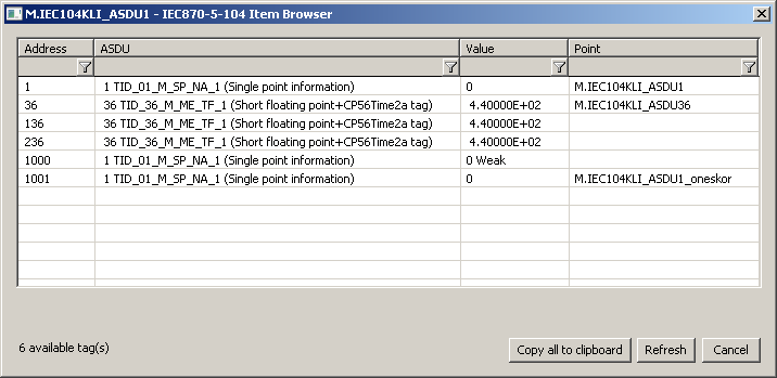
Browse
For the I/O tags, it is possible to discover the list of objects, as long as the KOM process is running and communication with a station is established.
Clicking the Browse button opens the IEC870-5-104 Item Browser window and displays a list of objects that have been read so far. The object list is created dynamically as a result of received messages.
The list of objects is dynamic, i.e. when a new value arrives in the KOM process, it is updated. Filtering in individual columns is also supported, asterisks can be used in the mask (e.g. *Short*).
Double-clicking on a particular line will cause the Address parameter to be inserted into the configuration of I/O tag from which the IEC870-5-104 Item Browser window was opened.
The Refresh button clears the list of values in both the CNF and the KOM process.
The Value column contains the received value.
Literature
-
Blogs
You can read blogs about IEC 870-5-104 protocol (for now, in Slovak language only):
Document revisions
- Ver. 1.0 – July 30th, 2003
- Ver. 1.1 – November 19th, 2003: extension of supported ASDU, new parameters
- Ver. 1.2 – March 20th 2004: added ASDU for reading archive data
- Ver. 1.3 – June 20th, 2004: extension - redundancy support
- Ver. 1.4 – December 1st, 2004: extension - support of balanced mode
- Ver. 1.5 - December 12th, 2012 - updating, tell commands
- Ver. 1.6 – June 15th, 2020: browsing support
Related pages: