IEC 60870-5-101 communication protocol
Supported device types and versions
Communication line configuration
Communication station configuration
Line protocol parameters
I/O tag configuration
Tell commands
Literature
Changes and modifications
Document revisions
Supported device types and versions
This protocol (known also as IEC 870-5-101 or IEC-101) supports:
- standard IEC 60870-5-101:2003 in both "unbalanced" (master and slave) and "balanced" modes,
- redundancy of communication lines according to the so-called Norwegian convention (Norwegian IEC 870-5-101 User Conventions).
Communication line configuration
Line categories:
- Serial,
- Serial Line Redundant,
- Serial System&Line Redundant,
- SerialOverUDP Device Redundant,
- SerialOverUDP Line Redundant,
- SerialOverUDP System&Line Redundant,
- RFC2217 Client.
Implementation is, according to the IEC870-5-101 standard, as follows:
- The originator ASDU address is not present.
- ASDU address is 1 byte, it is defined as the station address. ASDU addresses of all stations on one line must be different.
- The cause of transmission is 1 byte (does not contain Originator ASDU address).
- The information object address is 2 bytes, it is defined as an I/O tag address.
If a redundant communication on two lines is required (Norwegian conventions) use the line categories Serial Line Redundant or SerialOverUDP Device Redundant.
If you require the system-redundant communication, use SerialOverUDP System&Line Redundant or Serial System&Line Redundant line categories. Providing that, this communication should be also network redundant, enter "Secondary line" for both "A System" and "B System". This configuration then works in such a way that it concurrently sends and receives data from two systems and each is network-redundantly connected in compliance with the so-called Norwegian convention (Norwegian IEC 870-5-101 User Conventions).
Communication station configuration
- Communication protocol "IEC 870-5-101 balanced", "IEC 870-5-101 unbalanced primary (Master)" or "IEC 870-5-101 unbalanced secondary (Slave)".
- The station address is a decimal number in range 0 - 255 and is used in the protocol as the ASDU address.
- The synchronization of the station real-time may be enabled also for the protocols "master" and "balanced - station A (controlling)". Set the synchronization period to a nonzero value. The synchronization is executed by ASDU 103 "Clock synchronization command" in the local time according to settings of the D2000 System.
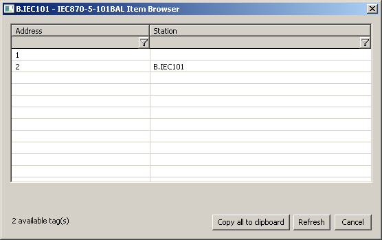
The Browse button opens a browsing dialog for the station address. If the communication is functional, a dialog with the ASDU addresses received so far is displayed. The Refresh button can be used to clear the list of received ASDU addresses.
Line protocol parameters
Configuration dialog box - tab Protocol parameters.
They influence some optional parameters of the protocol. The following station protocol parameters can be set:
Table 1
| Parameter | Meaning | Unit | Default value |
|---|---|---|---|
| Link Address | Common link address. | - | 1 |
| Length of ASDU Address | Length of ASDU address. | 1/2 byte(s) | 1 |
| Length of Link Address | Length of common link address. | 1/2 byte(s) | 1 |
| Length of Info Object Address | Length of info object address. | 1/2/3 byte(s) | 2 |
| Length of Cause Of Transmission | Length of "Cause Of Transmission". | 1/2 byte(s) | 1 |
| Retry Count | The delay between request retry in case of a communication failure. | - | 2 |
| Retry Timeout | The delay between retry of call in case of a communication error. | ms | 100 millisecond |
| Wait First Timeout | Delay after sending the request before reading the response. | ms | 100 millisecond |
| Wait Timeout | Delay between response readings until it is completed. | ms | 500 millisecond |
| Max. Wait Retry | Retry count of response reading until it is completed. | - | 6 |
| No Data Timeout | Delay of next call "Request user data class 1/2" if no data have been received (only master). | ms | 300 millisecond |
| Inactivity Timeout | Interval of connection monitoring. If no valid data have not been received, station status will go to a communication error. Switching of redundant devices in case of SerialOverUDP Device Redundant line (only slave). | ms | 5 sec. |
| Moxa Timeout | The switching interval of the redundant devices MOXA NPort in case of communication error (only master, balanced). | sec. | 10 |
| Source Flags | Set flags FI..FL according to the source of line. If SerialOverUDP System+Line Redundant is used, the values will have these flags:
Note: Flag was used in communication with redundant systems to distinguish the wrong values that were sent by a partner system, which was supposed to be passive and not to send nothing. | - | NO |
| No Output Flags | Activation of parameter results in ignoring flags FA..FH for output I/O tags. If this parameter is turned off, flags FA..FH are mapped to individual bits of a quality byte. | - | NO |
| Link Test Timeout | Interval of request sending "Test function for link" if timeout elapsed and no data telegrams were transferred (balanced only). | sec. | 10 |
Single Value In Spontaneous Answer | When sending spontaneous changes, these will be sent one-per-ASDU and they will not be cumulated into longer packets. The parameter was implemented to handle a bug in a particular TM1703mic. | - | NO |
Data Class | The class used for sending data (slave only). IEC 101 Master sends Class1 (high priority) and Class2 (normal) read data requests. Slave responds to them with data or a message that it has no data. In both Class1 and Class2 responses there is an ACD flag that the slave has Class1 data available. If set, the IEC 101 Master will then request Class1 data. The parameter affects behavior as follows:
The default value of the parameter is Class1. | - | Class1&2 Class1 Class2 Prio reply |
Single Request | Discard received data before sending a response (only slave). If a correct request is received and the IEC 101 Slave wants to send a response, it will clear the incoming queue before sending, if the queue has data in it. This parameter serves as a protection against various data duplications due to communication partner errors (e.g. OSI Monarch with RtuPing running during switching of active communication line). | - | NO |
| Send Confirmation Command | Type of sent confirmation to write value (only slave, balanced). | - 7(CONF) 10(TERM) 7(CONF) and 10(TERM) | 7(CONF) |
| Accept Confirmation Command | Type of record confirmation to be accepted successfully (only master, balanced). | - 7(CONF) 10(TERM) 7(CONF) or 10(TERM) | 7(CONF) or 10(TERM) |
| Max. MTU | Limitation of data packet size (only slave, balanced). | bytes | 220 |
| Phys. Trans. Direction | Setting a bit DIR in balance mode (only balanced). | Station A(Controlling) Station B(Controlled) | Station A(Controlling) |
| Single Byte Ack | Send single-byte ACK preferentially (0xE5). | YES/NO | NO |
| Interrog. Covers Counters | Send the call 100 and counter values on general interrogation (only slave, balanced). | YES/NO | YES |
| Send EOI | Send "end of interrogation command" to all ASDU (only slave). | YES/NO | YES |
| Send Interrog. in Sec. Direct. | Send general interrogation command in case of slave or balanced controlled station B (only slave, balanced). | YES/NO | NO |
Sinaut Mode | Communication for system Sinaut Spectrum, which requires non-standard behavior on redundant lines (different from the Norwegian convention). | YES/NO | NO |
System Redundancy: Manages A Status Address | Address of station and output I/O tag with the status of system redundancy. The format of the address is Station Address, I/O tag address, for example. "1,1003". The parameter is useful for SerialOverUDP System&Line Redundant lines, which enable communication with two independent control systems (e.g. main dispatching SED in Žilina and backup dispatching SED in Bratislava). The parameter enables one to ignore values that are received from the control system, which is inactive just now, providing that the application knows which one is active or inactive. It can know it e.g. based on the value of the input I/O tag with the defined value. This feature (information about active control system) will work providing that station with the output I/O tag of Dout type exist with the same addresses as is defined in this parameter and the application must write True into it if "System A" is active, or False if "System B" (configured on the system redundant line) is active. | - | |
| Full Debug | A high level of communication tracking, the received values of I/O tags and other debug information is shown. | YES/NO | NO |
I/O tag configuration
Possible value types of I/O tags: Ai, Ao, Di, Dout, Ci, Co, Qi
I/O tag address is a numerical address of data object IOA (in range 0 - 65535).
In case of command direction in master or balanced mode is necessary to configure a proper ASDU type:
| ASDU type | I/O Tag type |
|---|---|
| 45 - Single command | Dout |
| 46 - Double command | Dout, Co |
| 47 - Regulating step command | Dout |
| 48 - Set point command, normalised value | Ao |
| 49 - Set point command, scaled value | Co |
| 50 - Set point command, short floating point value | Ao |
| 51 - Bitstring of 32 bit | Co |
| 58 - Single command with time tag CP56Time2a | Dout |
| 59 - Double command with time tag CP56Time2a | Dout, Co |
| 60 - Regulating step command with time tag CP56Time2a | Dout |
| 61 - Set point command, normalised value with time tag CP56Time2a | Ao |
| 62 - Set point command, scaled value with time tag CP56Time2a | Co |
| 63 - Set point command, short floating point value with time tag CP56Time2a | Ao |
| 64 - Bitstring of 32 bit with time tag CP56Time2a | Co |
In case of slave or balanced mode je is necessary to configure je proper ASDU type in v data direction:
| ASDU type | I/O Tag type |
|---|---|
| 1 - Single-point information | Di, Qi (On/Off), Ai, Ci |
| 2 - Single-point information with time tag | Di, Qi (On/Off), Ai, Ci |
| 3 - Double-point information | Qi, Ai, Ci |
| 4 - Double-point information with time tag | Qi, Ai, Ci |
| 5 - Step position information | Ci, Ai * |
| 6 - Step position information with time tag | Ci, Ai * |
| 7 - Bitstring of 32 bits | Ci, Ai |
| 8 - Bitstring of 32 bits with time tag | Ci, Ai |
| 9 - Measured value, normalized value | Ai |
| 10 - Measured value, normalized value with time tag | Ai |
| 11 - Measured value, scaled value | Ci, Ai |
| 12 - Measured value, scaled value with time tag | Ci, Ai |
| 13 - Measured value, short floating point value | Ai |
| 14 - Measured value, short floating point value with time tag | Ai |
| 15 - Integrated totals | Ci, Ai |
| 16 - Integrated totals with time tag | Ci, Ai |
| 17 - Event of protection equipment with time tag | Ci, Ai, TiR ** |
| 18 - Packed start events of protection equipment with time tag | Ci, Ai, TiR *** |
| 20 - Packed single-point information with status change detection | Ci, Ai |
| 21 - Measured value, normalized value without quality descriptor | Ai |
| 30 - Single-point information with time tag CP56Time2a | Di, Qi (On/Off), Ai, Ci |
| 31 - Double-point information with CP56Time2a tag | Qi, Ai, Ci |
| 32 - Step position information with CP56Time2a tag | Ci, Ai * |
| 33 - Bitstring of 32 bits with CP56Time2a tag | Ci, Ai |
| 34 - Measured value, normalized value with CP56Time2a tag | Ai |
| 35 - Measured value, scaled value with CP56Time2a tag | Ci, Ai |
| 36 - Measured value, short floating point value with time tag CP56Time2a | Ai |
| 37 - Integrated totals with time tag CP56Time2a | Ci, Ai |
| 38 - Event of protection equipment with time tag CP56Time2a | Ci, Ai, TiR ** |
| 39 - Packed start events of protection equipment with time tag CP56Time2a | Ci, Ai, TiR *** |
| 40 - Packed output circuit information of protection equipment with time tag CP56Time2a | Ci, Ai, TiR *** |
Note 1: Individual bits of a quality byte (SIQ for ASDU 1,2,30; DIQ for ASDU 3,4,31; QDS for 5-14,20,32-36) set the attributes FLA (0.bit), FLB (1.bit) ..FLH (7.bit).
Example:
for ASDU 4: FLA=DPI bit 0, FLB=DPI bit 1, FLC=0, FLD=0, FLE=BL bit, FLF=SB bit, FLG=NT bit, FLH=IV bit.
for ASDU 16: FLA..FLE Sequence number bits 0..4, FLF=CY bit, FLG=CA bit, FLH=IV bit
Moreover:
- if bit IV (Invalid) is set, the status of value will be Invalid
- if one of the NT (Not topical), SB (Substituted), BL (Blocked), OV (Overflow), CA (Counter adjusted), or CY (Counter overflow) bits are set in their respective ASDU types, the status of value will be Weak.
* - T-bit from the value of ASDU sets the attribute FI into the value of I/O tag which has value type Ci/Ai and they are interpreted as numbers -64 up-to +63.
** - ASDU 17 and 38: the value of SEP byte sets the attributes FLA (0.bit), FLB (1.bit) up-to FLH (7.bit), following 2 bytes (CP16Time2a) are interpreted as a positive number (0-60 000) into the value of I/O tag with value type Ci/Ai or as a relative time (0-60 seconds) into the value of I/O tag with TiR value type.
*** - ASDU 18, 39 and 40: value of SPE(ASDU 18,39) or OCI (ASDU 40) byte sets the attributes FLI (0.bit), FLJ (1.bit) up-to FLP (7.bit). The value of byte QDP sets the attributes FLA (0.bit), FLB (1.bit) up-to FLH (7.bit), following 2 bytes (CP16Time2a) are interpreted as a positive number (0-60 000) into the value of I/O tag with value type Ci/Ai or as a relative time (0-60 seconds) into the value of I/O tag with TiR value type.
Note 2: When using the system and line redundant categories of lines, the status of line and station is formed by a logical sum of all used lines. It means, that if the redundant system consists of four lines and just one line is working, the status of the station and line is all right. The status of lines is presented with the help of special input or output I/O tag (of integer and real type, i.e. Ai/Ao/Ci/Co). The name of this I/O tag has this format: [line_name]_SystemStatus (e.g. for line L.Test it is M.Test_SystemStatus). The value of the I/O tag represents the binary format of the status of N-tuple lines. If the first three lines are okay but the last one does not work (SystemB/SecondaryLine) i.e. [FALSE, TRUE, TRUE, TRUE], I/O tag has the value 0b0111, i.e. 7.
The order of lines mapped to individual bits is [SystemB/SecondaryLine, SystemB/PrimaryLine, SystemA/SecondaryLine, SystemA/PrimaryLine].
Browse
For the I/O tags, it is possible to discover the list of objects, as long as the KOM process is running and communication with a station is established.
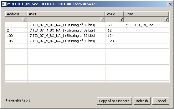
Clicking the Browse button opens the IEC870-5-101 Item Browser window and displays a list of objects that have been read so far. The object list is created dynamically as a result of received messages.
The list of objects is dynamic, i.e. when a new value arrives in the KOM process, it is updated. Filtering in individual columns is also supported, asterisks can be used in the mask (e.g. *Short*).
Double-clicking on a particular line will cause the Address parameter to be inserted into the configuration of the I/O tag from which the IEC870-5-101 Item Browser window was opened.
The Refresh button clears the list of values in both the CNF and the KOM process.
The Value column contains the received value.
Tell commands
| Command | Syntax | Description |
| STWATCH | STWATCH StationName | Tell command sends Interrogation Command (if it is configured/permitted for specific protocol). |
Literature
- Telecontrol equipment and systems Part 5-101: Transmission protocols – Companion standard for basic telecontrol tasks (IEC 60870-5-101:2003), http://www.iec.ch.
- Telecontrol equipment and systems Part 5-2: Link transmissions procedures (IEC 60870-5-2:1992), http://www.iec.ch.
- Norwegian IEC 870-5-101 User Conventions, Approved version Revision no. 2.0, http://www.statnett.no.
Blogs
You can read blogs about the IEC 870-5-101 protocol (for now, in Slovak language only):
Changes and modifications
- June 2015 - implemented Source Flags parameter
Document revisions
- Ver. 1.0 - November 22nd, 2007 - document creating
- Ver. 1.1 - April 22nd, 2009 - document updating
- Ver. 1.2 - June 8th, 2015 - new parameter implemented
- Ver. 1.3 – June 15th, 2020: browsing support
Related pages:
Pridať komentár