DLMS COSEM communication protocol
Supported device types and versions
Communication line configuration
Station configuration
Station parameters
Settings of transmission parameters
I/O tag configuration
I/O tag address
Literature
Changes and modifications
Document revisions
Supported device types and versions
This protocol executes a serial communication with the devices by binary HDLC protocol according to DLMS/COSEM standard.
Two modes of addressing of I/O tags are supported:
- "Short Name (SN) referencing" using 16-bit object addresses
- "Logical Name (LN) referencing" using 6-byte OBIS codes
Communication was tested with following devices:
- EMH LZQJ (SN referencing)
- Landis ZMD400 (SN referencing)
- Iskraemeco Iskra MT880-M (LN referencing)
- ADDAX NP73E.2-18-1 (LN referencing)
Protocol supports time synchronization, the period is configured in station configuration dialog.
Communication line configuration
- Supported line categories: Serial, SerialOverUDP Device Redundant, TCP/IP-TCP, TCP/IP-TCP Redundant, MOXA IP Serial Library, RFC2217 Client, MODEM.
Station configuration
- Communication protocol "DLMS/COSEM".
The station address (DLMS Server HDLC/MAC Address) consists of two parts: Upper MAC Address and Lower MAC Address. Each of them is in the range from 0 to 16383 (3FFFH).

As per a specification, DLMS UA 1000-2 Ed. 7.0 (Green Book) represents:
- Upper MAC Address is used for addressing a Logical Device, i.e. separately addressable entity within the physical device.
- Lower MAC Address is used for addressing of a Physical Device, i.e. multi-drop address on the line.
Upper MAC Address is required. An implicit value, which is set when missing the station address, is a reserved address Upper MAC Address = 1 (Management Logical Device).
In ordinary situations, when the physical device is identical with the logical one (one physical device = one logical device), you need not change this address. If the physical device integrates more logical devices, you should monitor the registry content "0-0:41.0.0" of "SAP assignment" class (class_id=17, attribute 2 "SAP_assignment_list") in the dialog box "DLMS SN Object List". This dialog box shows the list of logical devices that are integrated in the physical one.

This is the example of value representation of the attribute "SAP_assignment_list" of the class "SAP assignment" in the device which contains one logical devices with Upper MAC Address 16.
See also the protocol parameter "Client MAC address" and a document "DLMS UA 1000-2 Ed. 7.0", chapter 8.4.2.3 "Reserved special HDLC addresses".
Note: for Iskraemec Iskra MT880, Upper MAC Address = 1, Lower MAC Address = 16 + the last two digits of the serial number (if, for example, the serial number is 72211943, then Lower MAC Address = 16 + 43 = 59).
Station parameters
Communication station configuration dialog box - Protocol parameters tab.
It influences some optional protocol parameters. The following station protocol parameters can be set:
Table 1
| Parameter | Meaning | Unit / size | Default value |
|---|---|---|---|
| --- DLMS/HDLC parameters --- | |||
Application Context | Setting of "Application Context" parameter of DLMS/COSEM protocol. Short_Name_Referencing_No_Ciphering context is supported for "Short Name (SN) referencing". Logical_Name_Referencing_No_Ciphering context is supported for "Logical Name (LN) referencing". Next two contexts with encryption are not supported. | Logical_Name_Referencing_No_Ciphering Short_Name_Referencing_No_Ciphering Logical_Name_Referencing_With_Ciphering Short_Name_Referencing_With_Ciphering | Short_Name_Referencing_No_Ciphering |
Client MAC Address | HDLC MAC address of a client (i.e. D2000 KOM process). A default value is 10H which is the reserved value "Public client". See "DLMS UA 1000-2 Ed. 7.0" document, chapter 8.4.2.3 "Reserved special HDLC addresses". | 0 .. 7FH | 10H |
HDLC Max_info_field_length-receive parameter | Maximal length of one HDLC frame packet on the receiver from the device. When occurring some communication problems (e.g. checksum error and so on), we recommend you to decrease the value of this parameter. | 250 | |
HDLC Max_info_field_length-transmit parameter | Maximal length of one HDLC frame packet on the transmitter to the device. When occurring some communication problems (e.g. checksum error and so on), we recommend you to decrease the value of this parameter. | 250 | |
Client Max Receive PDU Size | Maximal length of PDU (data packet). One PDU can be divided into more HDLC frame packets according to settings of HDLC protocol parameters Max_info_field_length-receive parameter and HDLC Max_info_field_length-transmit parameter. Note: a specific electrometer (Landis ZMD400) only accepted value of 0, otherwise it returned rejected-permanent error during connection establishment. | 0 .. 65535 | 1200 |
No Disconnect | A Disconnect request will not be used after the readout of values from a device is finished. During next readout a connection establishment phase is omitted (HDLC mode-setting request and AARQ negotiation request). | YES/NO | NO |
Password | Device password. If entered, the "Low Level Security" authentication with the entered password is used within the AARQ Association Request. | ||
No Browsing | Ban of online selection from the list of objects, directly on device, through the DLMS Object List dialog box in configuration of I/O tag address. | YES/NO | NO |
Profile Data Optimization | Several electrometers implement optimization of time data when reading from profiles (class_id=7). The optimization means that only the first row of data contains a timestamp, others contain null. The time stamp of each row is equal to the previous row's time stamp plus the value of capture_period (4) attribute. If the value of this parameter is YES, the value of the capture_period attribute is read prior to reading the profile data. If the value of this parameter is NO, the content of the capture_period attribute is not read, but the KOM process relies on all profile rows to contain timestamps. If this is not the case, the profile data is not read, and the line logs contain error messages "turn on station parameter 'Profile Data Optimization'". | YES/NO | YES |
Opening Mode | Opening mode of connection with device. If device is configured so that it directly uses DLMS/COSEM protocol on the given interface, set "Direct HDLC". Mostly (e.g. when reading through IR opto interface by optical reading head) you must open the connection by IEC protocol in so-called "mode E" and then transfer to HDLC binary protocol (i.e. DLMS/COSEM). "Mode E", according to specification of IEC protocol, uses the following setting of the transmission parameters:
If "Opening Mode" is set on "IEC mode E", above mentioned transmission parameters must be set. As for Serial communication line, the parameters must be set in the line parameters "Mode 1". See the protocol parameter "Software 7E1". The setting of the baud rate on 300 Baud is not required when using the line of MODEM category. It uses so-called DTE speed, between PC and modem. If this speed is higher than 300 Baud, you have to activate "handshaking" parameter on RTS/CTS in proper line mode. If parameter "Direct HDLC" is set, any dynamic change of transfer parameters is not expected. You can use any Serial line mode and set it by parameter "Line mode" on the station. More information is mentioned in IEC 62056-21, Electricity metering - Data exchange for meter reading, tariff and load control - Part 21: Direct local data exchange, Annex E: "METERING HDLC protocol using protocol mode E for direct local data exchange". See also chapter "Setting of transmission parameters". | Direct HDLC IEC mode E | Direct HDLC |
| --- IEC Parameters --- | |||
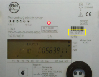
IEC Device Address | It is a station address (device) and is used only if Opening mode is set on "IEC Mode E". The parameter is optional. It identifies the address of device at the beginning of communication via IEC protocol. If this parameter is not defined, the address will not be set and the device will always respond. If several devices are connected to one line (e.g. RS485 bus), IEC address of device must be set so that the devices could be identified and avoid a collision. A device address is max. 32 characters consisting of figures (0...9), capital letters (A...Z), small letters (a...z) or blank space ( ). Zeros in front of valid figure are ignored (i.e. address 10203 = 010203 = 000010203). "IEC Device Address" is a serial number of device. This register has address "0-0:C.1.0" - Device ID 1, manufacturing number in OBIS addressing. The picture below shows the front panel of EMH LZQJ device. There is serial number, i.e. IEC address (563911). If device contains a display, this value may be displayed as you can see on the picture.
| - | |
Baudrate Changeover (Z) | This parameter is used only if Opening mode is set on "IEC Mode E". It defines baud rate for the communication through HDLC protocol DLMS/COSEM after changeover from IEC mode E to the HDLC binary communication. As for Serial line, this parameter must set the baud rate on "Mode 2". AUTO option sets the baud rate according to the value from a device. If this baud rate can not be identified, you should trace the diagnostic communication logs. You can find there the following message: 10:46:05.809 30-05-2011|D|DLMS> Z Detected: '4' = 4800 Bd and set the baud rate according to it. HDLC binary communication through DLMS/COSEM protocol unlike the opening IEC step is realized by different parameters which have to be set in "Mode 2" of the Serial line category:
See the parameter "Software 7E1" and the chapter Settings of transmission parameters. | 300 600 1200 2400 4800 9600 19200 AUTO | AUTO |
Software 7E1 | It is used if "Opening mode" is set on "IEC Mode E". YES option switches SW emulation of transfer parameters of 7 data bits, even parity when the transfer parameters of 8 data bits are set, none parity (i.e. emulation 7E1 when 8N1 is set). It enables to use "IEC mode E" option for SerialOverUDP lines that do not support a dynamic changes of transfer parameters. See the chapter Settings of transmission parameters. | YES/NO | NO |
Wake-up Message Length | It is used if "Opening mode" is set on "IEC Mode E". Nonzero value activates the sending of so-called "wake-up message" which activates the communication interface of battery-powered device. The null characters (0x00) are sent according to quantity that is characterized by the parameter value. The baud rate must be 300 Baud (select "Mode 1" for Serial lines). More information is mentioned in IEC 62056-21, Electricity metering - Data exchange for meter reading, tariff and load control - Part 21: Direct local data exchange, Annex B: "Wake-up methods for battery-operated tariff devices". | 0 .. 120 | 0 |
Delay After Wake-up Message | It is used if "Opening mode" is set on "IEC Mode E". If so-called "wake-up" message is activated, this parameter defines a delay after sending of "wake-up" message even before beginning of communication. As for Serial line, we recommend to set "WaitTxEMPTY" parameter in particular line mode. According to the document IEC 62056-21, you should set this parameter on 1,5 up to 1,7 s. | ms | 0 |
| --- Send/receive parameters --- | |||
Wait First Timeout | Delay after sending the request but before reading the response. | ms | 100 ms |
Wait Timeout | Delay between reading the till its completion. | ms | 200 ms |
Max. Wait Retry | Retry count of reading response till its completion. | 1 .. 100 | 20 |
Retry Timeout | Delay between the request retry if the error communication occurs. | ms | 500 ms |
Retry Count | Retry count of request as far as the error communication. | 1 .. 20 | 3 |
| --- Modem parameters --- | |||
Modem Telephone Number | Phone number for modem connection with a device (only for MODEM lines). | ||
Dial Timeout | Maximum waiting time for dial-up modem connection (only for MODEM lines). | 1 .. 600 s | 60 s |
Dial Retry Count | Maximum retry count of dial-up modem connection (only for MODEM lines). | 1 .. 20 | 1 |
Dial Retry Timeout | Delay before attempting to dial after an unsuccessful connection attempt (only for MODEM lines). | 1 .. 600 s | 30 s |
After Connect Delay | Time delay after the dial-up connection has been established (only for MODEM lines) but before the beginning of communication. It is used to stabilize the modem connection mostly as far as the old types of modems. After this timeout passes, all the redundant symbols (the residues of AT modem communication) will be read and ignored. | 0 .. 30 s | 5 s |
AT Command 1 | A special initial string of modem 1 (only for MODEM lines). | AT&FE0V1Q0B0X3L0M0 | |
AT Command 2 | A special initial string of modem 2 (only for MODEM lines). Explanation of recommended settings: S37=5 1200bps DTE-DTE speed - limits the speed for modems. Many devices use modems with limited transfer speeds and this setting can speed-up the connection establishment process. Higher transfer speeds must be negotiated individualy. &D2 DTR drop to hangup - for matching with tha parameter of modem line (line configuration, tab "Modem - parameters", check the option "Use DTR for Hangup"). S0=0 Disable auto-answer. Auto-answer will not be used. S30=2 20 sec inactivity timeout - automatic hangup after idle timeout expired. Necessary for assuring connection termination after the communication with the last device is over. | ATS37=5&D2S0=0S7=60S30=2 | |
| --- Debug parameters --- | |||
HDLC Debug | This parameter activates debug information from the HDLC protocol level. | YES/NO | NO |
Full Debug | This parameter activates full communication monitoring. It enables to display the I/O tag values and other debug information. | YES/NO | NO |
Settings of transmission parameters
Example 1 - line category Serial, the communication through IR optical head.
| Line mode 1 | 300 Baud, 7 data bits, 1 stop bit, even parity |
| Line mode 2 | 300 Baud, 8 data bits, 1 stop bit, none parity |
| Opening Mode | IEC mode E |
| Baudrate Changeover (Z) | 300 |
| Software 7E1 | NO |
Example 2 - line category Serial, communication through IR optical head.
| Line mode 1 | 300 Baud, 8 data bits, 1 stop bit, none parity |
| Line mode 2 | 300 Baud, 8 data bits, 1 stop bit, none parity |
| Opening Mode | IEC mode E |
| Baudrate Changeover (Z) | 300 |
| Software 7E1 | YES |
Example 3 - line category Serial, communication through RS232/RS485 interface.
| Line mode 1 | 4800 Baud, 8 data bits, 1 stop bit, none parity |
| Opening Mode | Direct HDLC |
I/O tag configuration
Possible I/O tag types: Ai, Ci, Di, TxtI, TiA, TiR.
I/O tag address
To understand the object addressing in DLMS/COSEM protocol, you should know so-called OBIS standard according to IEC 62056-61 Object Identification system (OBIS), Annex A - Code presentation.
The "Logical Name (LN) referencing" mode uses OBIS address of objects.
The "Short Name (SN) referencing" mode does not use OBIS address but a numerical address in the range of 16 bits.
The individual data entities are presented in so-called COSEM objects (Companion Specification for Energy Metering), which are the instances of COSEM classes (COSEM interface classes, COSEM IC). The types of COSEM classes are specified in the document "COSEM Identification System and Interface Classes, Ed. 10.0", i.e. DLMS Blue Book. Each COSEM class has own identification number ("class_id") and the attributes with the sequence number. The attribute helps to get a specific parameter of given data entity.
Each instance has its initial SN address (base_name), which is also the address of the first attribute of class. "logical_name" is the first attribute of all COSEM classes. When reading this attribute, a user can obtain OBIS address of data entity that is presented by given class. The address of other attributes are in the "Short Name referencing" mode calculated according to this formula:
short_name = base_name + ((attribute_index - 1) * 0x08)
The attributes can be static or dynamic depending on whether their value is static (i.e. unchanging, set by a producer or in configuration of device) or dynamic (changing). In D2000 System, we recommend to configure only the dynamic attributes as the value of measured data entity is in dynamic attributes. If it is necessary, for the interpretation of value in dynamic attribute, other static or dynamic attributes are read automatically. See more information in the section Supported COSEM classes.
In the following tables you can find the supported COSEM classes. The attributes that represents the value of data entity (i.e. value that is important for a user) are marked as "Yes, value of entity" in the column "Support in D2000". The static attributes are read automatically and characterized as "Automatically read".
Supported COSEM classes
| Data class_id = 1, version = 0 | Basic class that contains data entity accessible via attribute "value". | ||||
| Attribute | Attribute value type | Attribute description | Support in D2000 | ||
| 1. | logical_name (static) | octet-string (text) | OBIS address of data entity which is represented by an instance of this class. | Yes, separate I/O tag | |
| 2. | value (dynamic) | CHOICE (see supported types of attribute values) | The value of data entity. | Yes, value of entity | |
| Register class_id = 3, version = 0 | A class with data entity value that is accessible via attribute "value". The multiply coefficient, which is gained by static attribute "scaler_unit", is used automatically. | ||||
| Attribute | Attribute value type | Attribute description | Support in D2000 | ||
| 1. | logical_name (static) | octet-string (text) | OBIS address of data entity which is represented by an instance of this class. | Yes, separate I/O tag | |
| 2. | value (dynamic) | CHOICE (see supported types of attribute values) | The value of data entity. | Yes, value of entity | |
| 3. | scaler_unit (static) | - | Technical units and multiply coefficient. | Automatically read | |
| Extended register class_id = 4, version = 0 | class with data entity value that is accessible via attribute "value". The multiply coefficient, which is gained by static attribute "scaler_unit", is used automatically. A time stamp, which has been gained by the reading of dynamic attribute "capture_time", is added to the entity value. | ||||
| Attribute | Attribute value type | Attribute description | Support in D2000 | ||
| 1. | logical_name (static) | octet-string (text) | OBIS address of data entity which is represented by an instance of this class. | Yes, separate I/O tag | |
| 2. | value (dynamic) | CHOICE (see supported types of attribute values) | The value of data entity. | Yes, value of entity | |
| 3. | scaler_unit (static) | - | Technical units and multiply coefficient. | Automatically read | |
| 4. | status (dynamic) | CHOICE (see supported types of attribute values) | Status of the value. The standard does not specify the interpretation of this value. Mostly, it is a numerical value and you can find necessary information about its interpretation in a device manual. | Yes, separate I/O tag | |
| 5. | capture_time (dynamic) | date_time | Time stamp of data entity value. | Automatically read | |
| Demand register class_id = 5, version = 0 | A register for measurement of accumulation energy supply in given period. See more info in DLMS Blue Book. | ||||
| Attribute | Attribute value type | Attribute description | Support in D2000 | ||
| 1. | logical_name (static) | octet-string (text) | OBIS address of data entity which is represented by an instance of this class. | Yes, separate I/O tag | |
| 2. | current_average_value (dynamic) | CHOICE (see supported types of attribute values) | Current situation of energy supply that is accumulated since the beginning of the period. | Yes, value of entity | |
| 3. | last_average_value (dynamic) | CHOICE (see supported types of attribute values) | Value of energy accumulated in last period. | Yes, value of entity | |
| 4. | scaler_unit (static) | - | Technical units and multiply coefficient. | Automatically read | |
| 5. | status (dynamic) | CHOICE (see supported types of attribute values) | Status of the value. The standard does not specify the interpretation of this value. Mostly, it is a numerical value and you can fined necessary information about its interpretation in a device manual. | Yes, separate I/O tag | |
| 6. | capture_time (dynamic) | date_time | Time stamp of data entity value in the attribute "last_average_value". | Automatically read | |
| 7. | start_time_current (dynamic) | date_time | Time stamp of the beginning of accumulated energy measurement with current status in the attribute "current_average_value". | Automatically read | |
| 8. | period (static) | double-long-unsigned | Interval period between two changes in data entity value in the attribute "last_average_value". The value is in seconds. | Yes, separate I/O tag | |
| 9. | number_of_periods (static) | long-unsigned | Period count that are used for calculation of data entity value in the attribute "last_average_value". If "number_of_periods" > 1, "last_average_value" represents "sliding demand". If "number_of_periods" = 1, "last_average_value" represents "block demand". | Yes, separate I/O tag | |
| Clock class_id = 8, version = 0 | Current time and other time parameters. | ||||
| Attribute | Attribute value type | Attribute description | Support in D2000 | ||
| 1. | logical_name (static) | octet-string (text) | OBIS address of data entity which is represented by an instance of this class. | Yes, separate I/O tag | |
| 2. | time (dynamic) | date_time | Current local time. | Yes, value of entity | |
| 3. | time_zone (static) | long | Deviation of local time from UTC in minutes. | Yes, separate I/O tag | |
| 4. | status (dynamic) | unsigned | Time status: bit 0 (LSB): invalid value, bit 1: doubtful value, bit 2: different clock base, bit 3: invalid clock status, bit 4: reserved, bit 5: reserved, bit 6: reserved, bit 7 (MSB): daylight saving active | Yes, separate I/O tag | |
| 5. | daylight_savings_begin (static) | date_time | Time of passing from local time to daylight saving time (DST). | Yes, separate I/O tag | |
| 6. | daylight_savings_end (static) | date_time | Time of passing from daylight saving time to local time. | Yes, separate I/O tag | |
| 7. | daylight_savings_deviation (static) | integer | Deviation of DS time from standard time in minutes within the range +/- 120 minutes. | Yes, separate I/O tag | |
| 8. | daylight_savings_enabled (static) | boolean | TRUE = DST enabled, FALSE = DST disabled | Yes, separate I/O tag | |
| 9. | clock_base (static) | enum | Type of source type of exact time: (0) not defined, (1) internal crystal, (2) mains frequency 50 Hz, (3) mains frequency 60 Hz, (4) GPS (global positioning system), (5) radio controlled | Yes, separate I/O tag | |
| SAP assignment class_id = 17, version = 0 | Information about an assignment of logical devices. | ||||
| Attribute | Attribute value type | Attribute description | Support in D2000 | ||
| 1. | logical_name (static) | octet-string (text) | OBIS address of data entity which is represented by an instance of this class. For this case, it is always "0-0:41.0.0". | Yes, separate I/O tag | |
| 2. | SAP_assignment_list (static) | asslist_type | asslist_type is a structure array with addresses and text description "logical device name". It can be only in text format, i.e. I/E tag must be of TxtI type. See information about the station configuration. | Yes, separate I/O tag | |
| IEC local port setup class_id = 19, version = 1 | Information about the configuration of communication interface for the communication according to IEC 62056-21. | ||||
| Attribute | Attribute value type | Attribute description | Support in D2000 | ||
| 1. | logical_name (static) | octet-string (text) | OBIS address of data entity which is represented by an instance of this class. | Yes, separate I/O tag | |
| 2. | default_mode(static) | enum | It defines the protocol that is used by device on the port: (0) protocol according to IEC 62056-21 (modes A…E), (1) protocol according to Clause 8 of DLMS UA 1000-2 Ed. 7.0. Using this enumeration value all other attributes of this IC are not applicable, (2) protocol not specified. Using this enumeration value, attribute 4, prop_baud is used for setting the communication speed on the port. All other attributes are not applicable. | Yes, separate I/O tag | |
| 3. | default_baud (static) | enum | Baud rate in so-called "opening sequence": (0) 300 baud, (1) 600 baud, (2) 1 200 baud, (3) 2 400 baud, (4) 4 800 baud, (5) 9 600 baud, (6) 19 200 baud, (7) 38 400 baud, (8) 57 600 baud, (9) 115 200 baud | Yes, separate I/O tag | |
| 4. | prop_baud (static) | enum | Baud rate which is suggested by device. The values are the same as "default_baud". | Yes, separate I/O tag | |
| 5. | response_time (static) | enum | It defines minimal time between the receiving of request (the end of request telegram) and the sending of response (the beginning of response telegram): (0) 20 ms, (1) 200 ms | Yes, separate I/O tag | |
| 6. | device_addr (static) | octet-string | Device address for IEC 62056-21 protocol. | Yes, separate I/O tag | |
| 7. | pass_p1 (static) | octet-string | Password 1 according to IEC 62056-21. | Yes, separate I/O tag | |
| 8. | pass_p2 (static) | octet-string | Password 2 according to IEC 62056-21. | Yes, separate I/O tag | |
| 9. | pass_w5 (static) | octet-string | Password W5 reserved for national applications. | Yes, separate I/O tag | |
| IEC HDLC setup class_id = 23, version = 1 | |||||
| Attribute | Attribute value type | Attribute description | Support in D2000 | ||
| 1. | logical_name (static) | octet-string (text) | OBIS address of data entity which is represented by an instance of this class. | Yes, separate I/O tag | |
| 2. | comm_speed (static) | enum | Communication speed on the proper port: (0) 300 baud, (1) 600 baud, (2) 1 200 baud, (3) 2 400 baud, (4) 4 800 baud, (5) 9 600 baud, (6) 19 200 baud, (7) 38 400 baud, (8) 5 7 600 baud, (9) 115 200 baud | Yes, separate I/O tag | |
| 3. | window_size_transmit (static) | unsigned | The maximum number of frames that a device or system can transmit before it needs to receive an acknowledgement from a corresponding station. During logon, other values can be negotiated. | Yes, separate I/O tag | |
| 4. | window_size_receive (static) | unsigned | The maximum number of frames that a device or system can receive before it needs to transmit an acknowledgement to the corresponding station. During logon, other values can be negotiated. | Yes, separate I/O tag | |
| 5. | max_info_field_length_transmit (static) | long-unsigned | The maximum information field length that a device can transmit. During logon, a smaller value can be negotiated. | Yes, separate I/O tag | |
| 6. | max_info_field_length_receive (static) | long-unsigned | The maximum information field length that a device can receive. During logon, a smaller value can be negotiated. | Yes, separate I/O tag | |
| 7. | inter_octet_time_out (static) | long-unsigned | Defines the time, expressed in milliseconds, over which, when any character is received from the primary station, the device will treat the already received data as a complete frame. | Yes, separate I/O tag | |
| 8. | inactivity_time_out (static) | long-unsigned | From the primary station, the device will process a disconnection. When this value is set to 0, this means that the inactivity_time_out is not operational. | Yes, separate I/O tag | |
| 9. | device_address (static) | long-unsigned | Contains the physical device address of a device. In the case of one byte addressing: 0x00 NO_STATION Address, 0x01…0x0F Reserved for future use, 0x10...0x7D Usable address space, 0x7E ‘CALLING’ device address, 0x7F Broadcast address In the case of two byte addressing: 0x0000 NO_STATION address, 0x0001..0x000F Reserved for future use, 0x0010..0x3FFD Usable address space, 0x3FFE ‘CALLING’ physical device address, 0x3FFF Broadcast address | Yes, separate I/O tag | |
Historical data reading from load profiles
The reading of historical data from load profiles is made by the instances of COSEM classes "Profile generic" (class_id = 7), i.e. the configuration of I/O tag in attribute 2 ("buffer"). This I/O tag always contains the invalid valued in D2000 System but it enables to read a buffer of the instance of COSEM class "Profile generic".
| Profile generic class_id = 7, version = 1 | |||||
| Attribute | Attribute value type | Attribute description | Support in D2000 | ||
| 1. | logical_name (static) | octet-string (text) | OBIS address of data entity which is represented by an instance of this class. | Yes, separate I/O tag | |
| 2. | buffer (dynamic) | array | Data of stored objects. | Yes, see above mentioned | |
| 3. | capture_objects (static) | array | List of object, whose values are stored. | Automatic or separate I/O tag of TxtI type | |
| 4. | capture_period (static) | double-long-unsigned | Period of data storage in seconds. if the value = 0, data are stored by trigger, not automatically. | Yes, separate I/O tag | |
| 5. | sort_method (static) | enum | Method to sort data in profile: (1) fifo (first in first out), (2) lifo (last in first out), (3) largest, (4) smallest, (5) nearest_to_zero, (6) farest_from_zero | Yes, separate I/O tag | |
| 6. | sort_object (static) | It specifies the object or time according to which the data are sorted in a profile. | Yes, separate I/O tag | ||
| 7. | entries_in_use (dynamic) | double-long-unsigned | Number of records that have been saved into buffer of profile. | Yes, separate I/O tag | |
| 8. | profile_entries (static) | double-long-unsigned | Maximum records that can be stored into buffer. | Yes, separate I/O tag | |
Data about objects that are accessible by reading of attribute "capture_objects" are stored into buffer. D2000 System automatically searches I/O tags (its address parameters) that match the objects from attribute "capture_objects". The objects are searched by these parameters: "logical_name", "class_id" and "attribute_index".
TELL command GETOLDVAL or ESL action GETOLDVAL start the reading of all the configured load profiles on the station. The time interval with data is always read by the parameters of TELL command or ESL action from the load profile.
Supported value types of class attributes
| Type | Description, meaning | Supported conversion into D2000 value types |
| null-data | no data | all as invalid value |
| boolean | boolean (true/false) | Di, Ci, Ai, TxtI |
| bit-string | unsupported | - |
| double-long | 32 bit number signed | Di, Ci, Ai, TxtI |
| double-long-unsigned | 32 bit number unsigned | Di, Ci, Ai, TxtI |
| octet-string | string of bytes | TxtI |
| visible-string | string (text) | TxtI |
| UTF8-string | UTF8 string (text) | TxtI |
| bcd | unsupported | - |
| integer | 8 bit number signed | Di, Ci, Ai, TxtI |
| long | 16 bit number signed | Di, Ci, Ai, TxtI |
| unsigned | 8 bit number unsigned | Di, Ci, Ai, TxtI |
| long-unsigned | 16 bit number unsigned | Di, Ci, Ai, TxtI |
| long64 | 64 bit number signed | Di, Ci, Ai, TxtI |
| long64-unsigned | 64 bit number unsigned | Di, Ci, Ai, TxtI |
| enum | enumerated type | Di, Ci, Ai, TxtI |
| float32 | float 32 bit | Di, Ci, Ai, TxtI |
| float64 | float 64 bit | Di, Ci, Ai, TxtI |
| date-time | date + time | TxtI, TiA |
| date | date | TxtI, TiA |
| time | time | TxtI, TiA, TiR |
I/O tag address - configuration dialog box
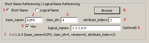
The following picture shows a configuration dialog box of I/O tag address.
Example for Short Name (SN) referencing:
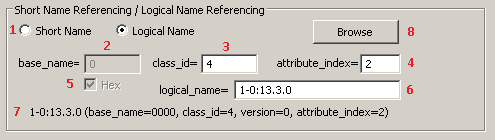
Example for Logical Name (LN) referencing:
The meaning of the parameters in dialog box:
| 1 | Selection of referencing: Short Name (SN) or Logical Name (LN). Based on the value of the station parameter Application Context the I/O tags with either SN or LN referencing will be handled. |
| 2 | SN referencing: required parameter, it is the initial address of class instance. It is an integer number within the range 0 up to 65520 (0xFFF0 hexadecimal). LN referencing: unused (disabled) parameter. |
| 3 | Required parameter, it is an identification number of COSEM class. |
| 4 | Required parameter, it is an index of attribute (a serial number from 1). |
| SN referencing: the parameters base_name, class_id and attribute_index are mandatory. The parameters base_name and attribute_index are used to calculate Short Name (SN) address according to the formula which helps to get the value of attribute from device. Class_id shows a type of COSEM class. Attribute_index identifies data type that were received from a device. LN referencing: parameters class_id, attribute_index and logical_name are mandatory. | |
| 5 | SN referencing: the checkbox Hex enables to enter the address base_name in hexadecimal form (checked) or decimal (unchecked). When editing the existing I/O tag, this checkbox is marked depending on the address that was entered in first configuration of I/O tag (i.e. hexadecimal or decimal). The change of status (checked/unchecked) does not convert automatically the value base_name from hexadecimal to decimal and vice-versa. LN referencing: unused (disabled) parameter. |
| 6 | SN referencing: the parameter logical_name is optional. It is OBIS address that belongs to Short Name address, configured by parameters base_name, class_id and attribute_index. It is in a text format according to OBIS specification of object address. |
| 7 | In the bottom part, there is information about the object address. Their meaning is only to inform the user about a configured object. The information is initialized after choosing the address in DLMS Object list dialog box. |
| 8 | Clicking on the button Browse enables to select the address from DLMS Object List dialog box. There are two methods on how to configure the addresses of I/O tags:
|
DLMS Object List dialog box
If these conditions are fulfilled - the device is connected to D2000 System, a communication station exists and the device communicates, you can define the parameters of I/O tag address by the selection of the object from the list of all objects on the device. List of objects is queried from the device:
- in SN referencing mode: from a special class "Association SN" with predefined address base_name 0xFA00
- in LN referencing mode: from a special class "Association LN" with predefined address logical_name 0.0.40.0.0.255
There is no need to configure any other I/O tags, just click on the button Browse.
First loading of the list takes upto several minutes depending on the baud rate. The window displays the information "Waiting for data...".
After data loading, the list of objects and their descriptions will show in the window:
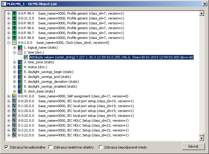
You can find the following information in the list:
- each row represents one instance of COSEM class,
- OBIS address of object follows the icon of class,
- then there is the information about SN address (base_name) of particular instance of COSEM class and about its type (class_id and version),
- COSEM classes, which are supported in D2000 System, can be expanded by clicking on symbol (+).
When expanding a specific instance of COSEM class, the supported attributes of class will be displayed:

The information about attribute includes:
- attribute index (attribute_index) - a sequential number of attribute, it is displayed next to the icon,
- attribute name (e.g. logical_name, value, scaler_unit, time_zone ...),
- static or dynamic attribute.
There can be an expand symbol (+) near the icon. When opening it and clicking on the row "Attribute value=", the current value of attribute will be retrieved from the device:

This feature enables fast browsing of the attributes of all supported COSEM classes. The dialog window works as both "Object List" and "Value Browser".
The bottom part of dialog box contains these check-boxes:
- Show hexadecimal - shows all the addresses of base_name classes as hex number or decimal one.
- Show inactive objects
- Show unsupported classes - enables to display the instances of unsupported COSEM classes.
To close the dialog box without any changes, click on Cancel button.
To insert the addressing parameters of attribute of instance into the address of I/O tag, double-click on the particular row. This closes the b dialog and the parameters will be set for the I/O tag.
OBIS address specification
The definition of OBIS address according to IEC 62056-61 is following:
| A | B | C | D | E | F |
- Value group A defines the energy type (0=abstract objects, 1=electricity, 7=gas),
- Value group B defines a channel number,
- Value group C defines a measured physical value,
- Value group D defines a type of processing,
- Value group E defines next processing or classification according to algorithm,
- Value group F defines storage of processed historical data.
Value group A up to F represents the integer number within the range from 0 up to 255.
For Value group C and D you can enter also the character values:
- character 'C' represents 96,
- character 'F' represents 97,
- character 'L' represents 98,
- character 'P' represents 99.
The address is written in text format:
A-B:C.D.E*F
Value group C, D and E must always contains the value. Other blank values will be set on zero (0).
For more information see "List of standard OBIS codes and COSEM objects" on http://www.dlms.com, the document "List of standardized OBIS codes, DLMS UA, V2.3, (c) Copyright 1997-2005 DLMS User Association".
Literature
- DLMS User Association, COSEM Architecture and Protocols, Seventh Edition, (c) Copyright 1997-2009 DLMS User Association (Green book).
- DLMS User Association, COSEM Identification System and Interface Classes, Ed. 10.0, (c) Copyright 1997-2010 DLMS User Association (Blue book).
- International Standard IEC 62056-21, Direct Data Local Exchange, First edition 2002-05.
- International Standard IEC 62056-61, Object Identification System (OBIS), Second edition 2006-11.
- List of standardized OBIS codes, DLMS UA, V2.3, (c) Copyright 1997-2005 DLMS User Association.
Blog
You can read blogs about DLMS protocol (for now, in Slovak language only): Communication - DLMS/COSEM protocol
Changes and modifications
-
Document revisions
- Ver. 1.0 - May 30, 2011 - creation of document.
- Ver. 1.1 - January 30, 2019 - suppor for LN referencing.
Related pages: