Supported device types and versions
Communication line configuration
Communication line protocol parameters
Communication station configuration
Station protocol parameters
I/O tag configuration
Literature
Changes and modifications
Document revisions
Supported device types and versions
Ethernet/IP protocol is one of the most widespread communications protocols in the US designed for communication with PLCs, motors, and other process-level devices. The protocol is managed and developed by ODVA, which includes companies such as Rockwell, Honeywell, or Schneider Electric.
Ethernet/IP protocol is an adaptation of the Common Industrial Protocol (CIP) for the Ethernet bus.
Implementation in D2000 supports:
- communication via TCP
- explicit messages (request/response type of communication)
- standard addressing of objects (Class/Instance/Attribute)
- symbol addressing of objects (proprietary Rockwell implementation)
- optimization of symbol objects addressing - so-called Symbol Instance Addressing
- optimizing the reading of multiple values using Multiple Service Packet Service messages
Implementation in D2000 does not support:
- communication via UDP
- implicit messages (I/O messaging)
The communication was tested with:
- Allen-Bradley Micro820
- 1769 CompactLogix 5370 Controller (1769-L18ER/A)
- ControlLogix EtherNet/IP bridge Module (1756-EN2TR/C) connected to 1756-L85E ControlLogix 5580 Controller (1756-L85E/B)
- SLC 5/05 1747-L553/C Ethernet Processor (in encapsulated PCCC mode)
- MicroLogix 1100 (in encapsulated PCCC mode)
Note: The Micro820 firmware version 6 only partially supported work with symbol addresses. Reading and writing worked, but browsing didn't - there was no class Symbol Object [0x6b]. Firmware version 10.0.12 supported browsing.
Note: CompactLogix 5370 supported work with symbol addresses, browsing as well as optimization of work in symbolic mode using Symbol Instance ID.
Communication line configuration
Category of communication line: TCP/IP-TCP
- TCP parameters - server parameters are mandatory:
- Host: server name in form of INET (name or numerical address a.b.c.d). In the case of redundant systems, multiple names/addresses separated by commas can be entered.
- Port: TCP port number (0..65535). The standard port of Ethernet/IP protocol is 44818
- Line number: unused, set to 0
Note: if all of the stations are in StOFF mode (or in simulation) on a TCP/IP-TCP line, the TCP connection will be closed. Thus it is possible to control TCP communication from the event using an STSTAT tell command.
Communication line protocol parameters
Configuration line dialog box - tab Protocol parameters.
They influence some of the optional protocol parameters. The following line parameters can be set:
Table 1
| Keyword | Full title | Description | Unit | Replacement value |
|---|---|---|---|---|
RT | Read Wait Timeout | Waiting between individual reads of data from the communication if no data has been received.. | sec.mss | 0.010 |
BS | Batch Size | The number of messages after sending of which the Send Delay is performed. | - | 1...1000 |
SD | Send Delay | Waiting after sending a batch consisting of Batch Size message. The purpose is not to overload the device with too many messages. Note: while testing the Micro820 device, problems were encountered when sending approximately 200 messages (browsing instances of the class File Object [0x37] with zero delay. Waiting for 1 ms solved the problem. | sec.mss | 0.001 |
MPR | Max Pending Requests | Maximum number of unacknowledged messages. If the number of unacknowledged messages reaches the value of the parameter, the KOM process waits before sending the next message. A value of 1 means that each message must be confirmed before sending another one (so that the PLC cannot be overloaded due to intensive communication). | 1..100 | |
SE | Write Symbolic: Array Elements | Methods of writing array using symbolic addressing (Rockwell). There are three supported modes:
| - | 0 .. Array Index |
OW | Optimized write of array element | Optimized write is used when only one array element is written. Optimization consists of writing only one specific element and specifying its index (in the protocol specified as Member ID). Note: the tested Micro820 device supported the optimization, the test software server did not. | - | False |
MP | Max Packet Size | The maximum size of Ethernet/IP messages (Unconnected Explicit message) - according to the standard 504 bytes. Note: in symbolic mode (Rockwell) it is also possible to work with larger arrays using proprietary services Read Tag Fragmented Service and Write Tag Fragmented Service. Note: this size does not include the Encapsulation Header (24 bytes - Command/Length/Session Handle/Status/Sender Context/Options) or the SendRRData/Common Packet Format header (16 bytes - Interface Handle/Timeout/Item1 + Length/Item2 Length). | Bytes | 504 |
RS | Response Timeout | Timeout to receive an answer for a request. If the response for a request is not received within this time, this is considered an error, and the TCP connection will be closed. | sec.mss | 10.000 |
SO | Optimized Work with Symbolic Names | Optimization of work in a symbolic mode (Rockwell) - so-called Symbol Instance Addressing. Instead of using symbolic names, a Symbol Instance ID is used for reading. The Symbolic name is converted to the Instance identifier by the same service which is used for browsing. Note: Not every device or Rockwell firmware version supports this optimization (tested Micro820 with firmware 10.0.12 or 11.0.11 did not support this optimization). In this case, if the device returns the Service not supported [0x08] error code, the optimization will be disabled until the KOM process is restarted or the configuration of the respective line is re-saved. | - | False |
Communication station configuration
- Communication protocol: Ethernet/IP.
- The station address is not configured. Multiple stations may be configured on a single line (e.g. because of different time parameters of individual stations).
Station protocol parameters
Communication station - configuration dialog box - tab Protocol parameters.
These parameters influence some optional parameters of the protocol. You can set the following station parameters:
Table 2
| Parameter | Meaning | Unit / size | Default value |
|---|---|---|---|
Route Path for Unconnected Send (hex) | An octet string representing the parameter Route_Path (of padded EPATH type, that is, the number of octets in each segment must be even). If this parameter is specified, the protocol messages (Get_Attribute_Single, Set_Attribute_Single, Read Tag [Fragmented] Service, Write Tag [Fragmented] Service) will be wrapped in an Unconnected Send message that is used for routing. It was not necessary to set this parameter when communicating with Micro820, MicroLogix 1100, and CompactLogix devices. When communicating with ControlLogix via the ControlLogix EtherNet/IP bridge Module (1756-EN2TR/C), it was necessary to set the parameter to 01 00, which according to protocol documentation means Port 1 (which represents the backplane) and slot 0 (where the Central Processor was located). To communicate with the processor in slot 1, the parameter had to be set to 01 01, so the general syntax for accessing a slot XX would be 01 XX. A more complicated configuration consisting of 3 segments:
so the whole Route Path string is: 01 00 12 0C 31 37 32 2E 32 35 2E 35 38 2E 31 31 01 01 (in the syntax of Rockwell OPC server it is "1,[0,2,172.25.58.11, 1], 1") | octet string | |
Use Multiple Service Packet Service | Setting the parameter to YES causes the protocol messages (Get_Attribute_Single, Set_Attribute_Single, Read Tag [Fragmented] Service, Write Tag [Fragmented] Service) to be wrapped in a Multiple Service Packet Service message. This parameter is used for communication optimization (wrapping several messages into one), while the size of one message (Unconnected Explicit message) does not exceed the Max Packet Size value. | YES/NO | NO |
PCCC Max Data Length | Setting the parameter to a non-zero value causes the use of the PCCC protocol encapsulated in the Ethernet/IP protocol. In this way, it is possible to communicate with older SLC 5/05 and PLC5E. At the same time, the symbolic address of the I/O tag starts to be interpreted as an address in SLC-500 format - see Allen-Bradley CSP/PCCC protocol (e.g. N:3 or $T4:0/ACC). | 0-240 bytes | 0 |
PCCC Command Set | Selection of PCCC commands used for communication with older SLC 5/05 and PLC5E if the PCCC Max Data Length parameter is set to a non-zero value. The following options are available for selection:
* - when using these commands, only writing is supported for the file types Status (S), Binary (B), Integer (N), Float (F), and even for these types only writing of whole elements is supported, not bits. Writing is not supported for the Timer (T) and Counter (C) file types. | - |
I/O tag configuration
Possible value types of I/O tag: Di, Ai, Ci, TxtI, TiR, TiA, Dout, Ao, Co, TxtO, ToR, ToA
The addressing of the I/O tag can be either standard or symbolic (Rockwell).
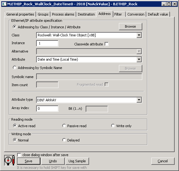
Standard addressing - Addressing by Class / Instance / Attribute
This addressing method uses messages defined by the CIP standard:
- Get_Attribute_Single [0x0E]
- Set_Attribute_Single [0x10]
Within these messages, an item is addressed by the class number (Class), the instances within the class (Instance), and the attribute number of the particular instance (Attribute).
Class - a selection of object class. The class can be selected from the list or entered numerically (16-bit unsigned number). In addition to the classes defined in the CIP protocol, some proprietary Rockwell classes are also supported.
Instance - specification of the instance number (32-bit unsigned number).
Classwide attribute - if this option is selected, the instance is not specified, and instead of the attributes of a particular instance, it is possible to work with classwide attributes (attributes related to the class).
Alternative - according to the standard, some classes have alternatives (e.g. depending on class revision, subclass, etc.). If this option is enabled, an alternative must be selected.
Attribute - an attribute, a value of which is to be read or written. The attribute can be selected from the list or entered numerically (32-bit unsigned number). The list of attributes depends on the Class, Classwide attributes, and Alternative.
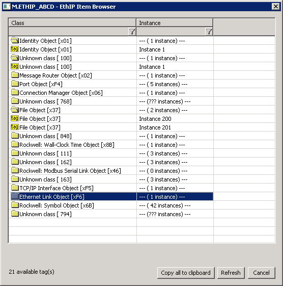
By clicking the Browse button, a browse dialog can be opened and a list of classes and instances within the class can be retrieved as long as communication with the device is established. When opening, only a list of classes (rows with the folder icon) is read for speed reasons. Double-click on a class retrieves a list of instances (if the number of instances was determined, i.e. it is not zero or unknown - "???"). Double-clicking on a specific instance (lines with the tag icon) copies the class and the instance to the configuration dialog of the I/O tag.
Note 1: the number of actually retrieved class instances may be less than the number displayed within the list of classes.
Note 2: browsing attempts to read all instances of 1 .. Max Instance, where Max Instance is detected when reading a list of classes. However, if Max Instance > 1000, only the first 1000 instances are tested during browsing. Reading of all instances can take up to several tens of seconds. When it is finished, the folder icon is changed from closed to open.
Note 3: In versions from 20th December 2018 and newer, the recycling of browser dialog has been implemented. If the dialog is closed by the Close button or after selecting an instance, it is actually only hidden and it is available for browsing by another I/O tag within the same station so that the tree structure of the browsed objects is preserved. Clicking on the close icon at the top right corner will cause the dialog to be really closed.
The Refresh button is used to repeatedly retrieve the list from the device. The KOM process caches a list of classes and instances, so the second and subsequent opening of the browse dialog or reading of the list of instances for a specific class is significantly faster than the first one during which the data is being read from the device.
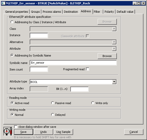
Symbolic Addressing - Addressing by Symbolic Name
This addressing method is supported by Rockwell devices. It uses Proprietary Rockwell messages:
- Read Tag Service [0x4C]
- Write Tag Service [0x4D]
- Read Tag Fragmented Service [0x52]
- Write Tag Fragmented Service [0x53]
- Execute PCCC [0x4B] - communication with older SLC 5/05 and PLC5E, see the PCCC Max Data Length parameter
While browsing the proprietary Rockwell message Get Instance Attribute List [0x55] is used. Some devices or firmware versions do not support this message or the Symbol Object [0x6b] class that the message uses.
Symbolic name - a symbolic name. It can be simple (Test) or contain the address of a specific item of a one-dimensional array (Test [3]), multidimensional (Test [1] [2]), item of a structure (Test.MyItem1), or item of an array of structures (Test[2].MyItem1).
If the PCCC Max Data Length parameter is set to a non-zero value, the symbolic address of the I/O tag starts to be interpreted as an address in SLC-500 format - see Allen-Bradley CSP/PCCC protocol (e.g. N:3 or $T4:0/ACC). Other settings (Fragmented read) are unused. Item count setting and reading items into the structure are supported (except for Input and Output file types). Writing values is also supported, and it is not necessary to set the Attribute type (and if it is set, it is ignored).
Item count - number of elements in the case of an array of values. This number may be less than or equal to the actual size of the array in the device. If it is not specified, one element is read.
Fragmented read - indication that the Read Tag Fragmented Service message should be used for reading because the entire array does not fit into a message with the length specified by the Max Packet Size parameter.
Note: If the reading using the Read Tag Service message returns an error code Partial Transfer [0x06], the next reads will use the Read Tag Fragmented Service message as if the Fragmented read indication was set.
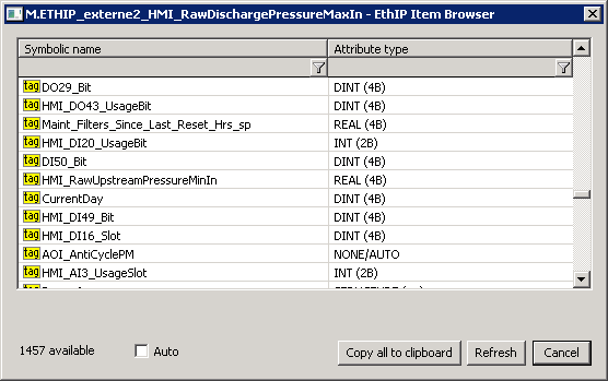
By clicking the Browse button, a browse dialog can be opened and a list of symbolic names retrieved as long as the communication with the device is established. For each symbolic name, its type is also read. In the case of structures or arrays of structures, the type is identified as "STRUCTURE (---)". D2000 cannot presently use such complex types - it is necessary to specify an address of a particular item as a symbolic name (e.g. MyStruct.MyItem or MyArr [1] .MyItem).
The Auto option is used to set the NONE/AUTO attribute type (autodetect). If this option is off, the attribute type is copied to the I/O tag along with the symbolic name after double-clicking on a specific line in the list of symbolic names.
The Refresh button is used to repeatedly retrieve the list from the device. The KOM process caches a list of symbolic names, so the second and subsequent opening of the browse dialog is significantly faster than the first one during which the data is being read from the device.
Note: symbolic names beginning with the underscore are related to system objects of the Rockwell device, other names are user-defined.
Atribute type - the type of attribute. In the case of standard addressing, it is necessary to enter a specific type. In the case of symbolic addressing, it is possible to leave the type of the attribute as NONE/AUTO (autodetect), since proprietary Rockwell messages contain both the value and the attribute type. An exception is if the I/O tag is write-only - then the attribute type must be specified.
Note: not all types of attributes from the offered list have reading/writing implemented. All numeric types, time types, strings (SHORT_STRING, STRING, STRING2), and numeric and time array types are supported. International string (STRINGI) type is supported for reading.
Array index - index of an element in an array, if the attribute is an array. In the Ethernet/IP protocol, an array is indexed from zero, so if the Item count is equal to 3, indices 0, 1, and 2 are allowed.
Note: if Array index + 1> Item count, then Array index + 1 element will be read instead of Item count.
Bit (1..n) - if an attribute type is an unsigned number (BOOL, USINT, UINT, UDINT, ULINT, DATE, TIME_OF_DAY, BYTE, WORD, DWORD, LWORD, ENGUNIT, and arrays of these types) it is possible to enter a specific bit (1 to 64, depending on the number of bits for a specific type).
Reading mode - a way to read the I/O tag. There are three ways of reading:
- Active read - the I/O tag generates read requests.
- Passive read - the I/O tag does not generate read requests, but it processes values read by another I/O tag with the same Class/Instance/Attribute address or Symbolic name. This mode makes sense for reading arrays, where a single I/O tag can be active and the other I/O tags are passive, so values of all (or selected) array items are read with one request.
Note: the Ethernet/IP protocol supports the reading of arrays into the structure (Destination tab), so it is possible to read the entire array into the column of a structure using a single I/O tag. - Write only - the I/O tag is intended only for writing.
Writing mode - a way of writing the I/O tag. This parameter only applies to output I/O tags (Dout, Ao, Co, TxtO, ToR, ToA).
- Normal - writing to the I/O tag will cause the write request to be sent.
- Delayed - writing to the I/O tag will be deferred and executed only as part of the writing of another I/O tag with the same Class/Instance/Attribute address or Symbolic name. This mode makes sense for writing to arrays, when multiple array elements are written using deferred I/O tags, and then writing to a Normal I/O tag generates a single request to write a complete array.
Note 1: if it is necessary to read the entire array MY_ARR (to the destination structure or to multiple I/O tags), it can be done by a single read request (unless the array is too large). Set in the first I/O tag configuration:
- Symbolic name: MY_ARR
- Item_count: number of array items (e.g. 10)
- Array index: not specified or 0
- Reading mode: leave as Active read
The first array item (with index 0) is read into this I/O tag. To read an array into a structure, specify the Destination column parameter in the Destination tab. To read array items into other I/O tags, configure them as follows:
- Symbolic name: MY_ARR
- Item_count: not specified
- Array index: 1 to 9
- Reading mode: change to Passive read
Note 2: When working with the ControlLogix 5580 Controller, there was a need to read multidimensional arrays. The MY_ARR field had dimensions [0..7] [0..3] [0..23]. Settings for reading an array (always 24 values at once) in the first I/O tag configuration:
- Symbolic name: MY_ARR[1][2][0] (for reading indices [1][2][0..23])
- Item_count: 24
- Array index: not specified
- Reading mode: Active read
Settings for I/O tags 1 to 23:
- Symbolic name: MY_ARR[1][2][0] (i.e. the same as for 0-item)
- Item_count: not specified
- Array index: 1 to 23
- Reading mode: change to Passive read
The Symbolic name had to contain all three indices, i.e. specification MY_ARR[1][2] didn't work.
Literature
THE CIP NETWORKS LIBRARY, Volume 1, Common Industrial Protocol (CIP™)
THE CIP NETWORKS LIBRARY, Volume 2, EtherNet/IP Adaptation of CIP
THE CIP NETWORKS LIBRARY, Volume 7, Integration of Modbus Devices into the CIP Architecture
Micro800 Programmable Controllers: Getting Started with CIP Client Messaging, Rockwell Automation
Logix 5000 Controllers Data Access (Programming Manual), Rockwell Automation
RSLogix 500 Getting Results Guide, Rockwell Automation
Blogs
You can read blogs about the Ethernet/IP protocol:
Changes and modifications
-
Document revisions
- Ver. 1.0 - November 28, 2018 - Creating of the document.
- Ver. 1.1 - January 2, 2019 - Improved browsing, testing with 1769 CompactLogix 5370 Controller
- Ver. 1.2 - September 6, 2021 - Support for encapsulated PCCC mode (read-only)
- Ver. 1.3 - December 21, 2021 - Support for reading items into the structure for PCCC mode
- Ver. 1.4 - January 4, 2021 - Support for writing in encapsulated PCCC mode
Related pages:
Pridať komentár