"Object configuration" dialog box
A dialog window is intended for a configuration of objects (flows) in a graph. A number placed in the header represents the object sequential number.

Active graph object
Active graph object is used to display the values of one row of a structured object. Row number can be
changed directly from the graph opened in process
D2000 HI - the button  in the graph window.
If a graph containing an active graph object is placed in picture as displayer, the row number of the active object can be controlled from the picture script, too. The row number, in dependence on the displayer configuration, can be also derived from the picture instance number.
Note: Graph containing active object becomes so-called active graph.
Alternate graph object
Alternate object is a special default "object". The object reserves a place for the graphic flow, data of which are gained from the script of the picture, where the corresponding graph is placed. Displaying and contents of this object is defined in the picture script. A graph does not contain this object until it is activated from the script. Its label is "*".
Object name
An object, values of which will be drawn in the graph window, may be defined in two ways. The first way
is typing the object name into Object name input edit box. The other way is selecting the object
from the list of objects opened after clicking the arrow button located right to the input box.
Note: If a defined object is a structured type, it is necessary to define a column (the parameter Column)
and a row (the parameter Row).
Row
Definition of a row of defined structured object.
Note: If it concerns about active object, the option Row is disabled.
Column
Definition of a column of defined structured object.
Description
Description of the given object which will be shown in the graph
table - the column Name. It is possible to use the Dictionary (to open press CTRL+L).
If the parameter is not entered, the graph table will contain the
description defined in the object configuration* (the parameter Description). If there is no
description defined in the object configuration, the table graph will show the object name.
* For structured objects - if a structured object is archived, or it uses
the reference to object which is archived, the description or the name of
object from the archive will be used. This description is obtained based on
the archived object. Mostly it is obtained from the definition of object,
which is archived. If structured object is not archived, the column description
from the structure definition
will be used. If this column does not exist, the description of the structured object with the row number
and column name will be used.
* For structured archive objects - there is used the description or name of
object from archive. This description is obtained based on the archived
object. Mostly it is obtained from the definition of object, which is
archived. Name of the column structured archive object does not includes the
name of column.
Note: The description in the graph table may be modified from a
script.
Units
Technical units of the objects, values of which are to be displayed in the graph. Technical units
will be shown in the graph table - the column Units.
If the parameter is not entered, the graph table will contain the technical units defined in the
object configuration* (the parameter Technical units). If there is no technical units defined
in the object configuration, the table graph will show no technical units.
* For structured objects - if the structured object is archived, there will be used the technical units
defined for respective archive object (object of Historical value type). If is not archived,
there will be used the technical units defined in the configuration of the structured object.
U.C.
The parameter allows to define content of the column Universal. Items of the parameter are described for the parameter Table columns.
Enable drawing
If the option is checked off, the graphic flow of the object will be drawn immediately after opening the graph on D2000 HI desktop. If not checked off, the graphic flow will not be displayed after opening the graph (can be enabled later from the graph window).
Visible in table
Shows / hides the object in the graph table.
If the parameter is not checked off, the object will not be displayed in the graph table but its flow will
be displayed.
Interactive
If the option Interactive is checked off and the User places mouse pointer on some value in the graph, this value is emphasized by circle.
Tooltip
Placing the mouse pointer on some value in the graph the window with activity name and its value will be displayed.
Note: Option Tooltip is visible only if the option Interactive is checked off.
Drawing order
The parameter defines an order of flow drawing. If the same value is set for more flows, they are drawn according to the serial number.
Draw
Selection the parameters for graph drawing. By marking the individual parameters is possible to define the particular parameters of drawing. The options for definition are displayed in the right part of configuration window. Only parameters for line, fill and marker can be defined together.Line
Defines the colour, style (solid line, dotted line, ...), transparency (0-transparent, 100-opaque) and line width in the range of 0,5 - 5,5 multiple of a point width on the screen.
Fill
Fill pattern of the line and transparency (0-transparent, 100-opaque).
Markers
Defines colour, type (6 types), transparency (0-transparent, 100-opaque) and highlighting of the marker.
Value
Defines the parameters for displaying of numerical value in graph.

| Text | - color of the text |
| Frame | - enable / disable to draw a frame and to define its color |
| Fill | - enable / disable the fill and its color and opaque |
| Font | - font type |
| Position | - position of the text in regard to position of presented value in graph |
| Only for last value | - enable / disable to display only the last value or all values |
Bar graph
There are several settings that are defined for a graphic flow of Bar graph type and they are distinctive for this graph type.

1 - setting of the color transparency, 0-transparent, 100-opaque.
Function
One column of bar graph need not represent just one object value but a whole group of values. Column
height is given as a result of a function applied on whole group of values. You can choose from the
following functions:
- By value
- Average
- Weighted average
- Sum total
- Maximum
- Minimum
- Count
- Last value
For the function By value, bars are drawn only once for each value on the position corresponding
to the value time. If the graph contains several flows of Bar graph type, bars are drawn not to overlap each
other. Bar width is calculated so that a group of bars for one time is drawn in front of drawing next group
of bars.
Requirements:
- The function can be used only for graphs having Live data parameter unchecked.
- If the function is used, then it must be used for all graphic flows of Bar graph type in the graph.
- The parameters Period is disabled for the function.
For correct functionality:
- Data must not be periodical, but they should be almost equally spread on time axis (e.g. monthly data in annual graph – they are not periodical).
-
If the graph contains several such flows, then:
- their numbers of values must be the same
- values must start in the same time
Bar drawing modification - bar width can go to 1 pixel. This modification eliminates the probability of drawing several values in one bar (in case, that there are several values in space required for drawing a bar).
Period
The parameter specifies the minimum possible period for drawing a bar. But current displayed period may be
larger in dependence on the current width of time axis. Current period will always be multiple of this
period.
Limits
Limits are defined only for a graphic flow of Bar graph type. Graph definition allows to use a color
resolution of values according to its position. The value may be:
- below the lowest limit (VLL - Very Low Limit),
- between the lowest and low limits (LL - Low Limit),
- between low and high limits - normal status,
- between high and the highest limits (HL - High Limit),
- above the highest limit (VHL - Very High Limit).
One color may be assigned to each of the limits. Values between defined limits (normal status) are drawn in the color chosen for the graphic flow in the Object configuration dialog box.
The way of displaying values according to the limits as described above, may be disabled - Do not
use option.
Checking From archive option allows to use values of the limits defined during the configuration
of an object:
- that has been archived (for example VLL, LL, HL and VHL values are used for object of the User variable type),
- that has been selected for graphic displaying.
The option Use defined allows to define the limits directly by typing into the LL, VLL, HL and VHL input edit boxes.
Strip graph
Strip graph is suitable to display time flows of alarms, eventually other objects that acquire discrete values. Digital axis have to be assigned to strip graph. There are defined several settings for strip graph, that are other than other types of graphs.

Draw within full digital axis level height
The parameter allows to draw strips of the graphic flows either within full height of the digital axis level
or only within one half of the level (older versions of D2000 system).
Defines the border of the flows, colour and frame width in the range of 0,5 - 5,5 multiple of a point width on the screen.
Value
The dropdown box consists the list of possible values of the object the flow of which will be displayed. Maximum number of values is 10. You must define a mode of displaying of each value by means of Color, Pattern and Opaque (0-transparent, 100-opaque). Selecting empty pattern disables displaying the strip for particular value.
Candlestick / OHLC graph / BoxPlot

Graph works in two modes:
- Changed - period is 0
If the value changes the column is drawn whereby the color of column depends on positive, none or negative change.

- Statistic - period differs from 0
Within the range, according to set period, it calculates an open, maximum, minimum and close value from input data. These values are represented by column bar that illustrates range of open and close value, and by thin lines that illustrates maximum and minimum of value within the given time period. If the checkbox Discrete values is checked off, the first new valid value from the interval is considered as open value. If the checkbox is not checked off the value valid at the began of open interval is considered as the open value of the interval.
Example of candlestick graph:

Example of OHLC graph:

BloxPlot graph
In descriptive statistics, a box plot or boxplot is a convenient way of graphically depicting groups of numerical data through their quartiles. Middle rectangle part (box) is bounded by the first and third quartiles, inside the box there is a line that draw a median. Boxplots may also have lines extending vertically from the boxes (whiskers) indicating the lowest data 1,5 * IQR of the lower quartile and the highest data 1,5 * IQR of the upper quartile. Individual outliners are plotted as small circles, extremely distant points as x marks. In configuration dialog you must define a period (unit and quantity), which defines an interval for calculation of statistics and display of one column. You may also define color and width of lines and fill of middle part (below and above the median).
Example of BoxPlot graph:

Link
Link between the points in graph can be:- Straight
- Smooth
Types of graphic flows
You can choose from the following types of graphic flows:
- Simple
- Additive
- Subtractive
- Sign
Note: Additive, subtractive and sign graphs calculate a flow by addition (subtraction) to the calculated value of the previous additive (subtractive) flow. Undefined value is understood as zero value. In case of sign graphs there will sum separately the plus items of the flow and plus items of previous flow, and minus items of the flow and minus items of previous flow (example of sign graph is mentioned below).
Graph samples:
 |
 |
 |
||
| smooth line graph | straight line graph | bar graph |
 |
 |
|
| marker graph | strip graph |
Other types are in the following figure:

Example of sign addition:
Settings the flows:

Data:
flow 1: 50,30,-50
flow 2: -10,10,20
flow 3: -30,20,-20
flow 4: 0
Result:

Additive / Subtractive
Ancestor
The parameter defines a serial number of an object from list
of objects - the graphic flow of the object will be added (subtracted) to (from) this defined ancestor.
The zero value of the parameter means that the ancestor is to be the nearest object (with an additive /
subtractive type of graphic flow) above the actual object in the
list of objects.
To add (subtract) the flow to (from) the ancestor's flow, the values of the parameters
Assigned axis and Drawing must be identical for both
flows.
Note 1: The parameter is only enabled for additive or subtractive graphs (see the parameter
Types of graphic flows).
Note 2: Undefined value is understood as zero value.
Hide with ancestor
If the parameter is checked off and the graphic flow of given object is hidden in the graph and the user hides
the flow of the ancestor, it also hides the graphic flow (as well as the flow of the object (with the
parameter checked off) that is "successor" to given object, etc.).
If the flow is hidden in the graph in the way described above, showing the flow of its ancestor shows the
flow too.
Note: the actions described above are recursive for all successors.
Example:
There are three objects defined in a graph: Obj1, Obj2 and Obj3. The object Obj1
is the ancestor to the object Obj2 and Obj2 is the ancestor to the object Obj3. All
the objects have the parameter Hide with ancestor checked off in their configuration and are visible in
the graph.
Hiding the flow of the object Obj1 in the graph hides the flows of the objects Obj2 and
Obj3. And then showing the flow of the object Obj1 shows the flows of the objects Obj2
and Obj3.
Draw from ancestor
If the parameter is checked off, the graphic flow (additive/subtractive) will be drawn from its ancestor no
matter, whether the ancestor is shown or hidden in the graph..
For correct functioning, the parameter Add /
subtract also hidden must be checked off too.
Example:
There are three objects defined in graph. The object Obj1 is
the ancestor to the object Obj2 and
Obj2 is the ancestor to the object Obj3.
The graphic flows of the objects are shown on the figure 1.
Figure 2: the flow of Obj2 is hidden and
Obj3 has the parameter Draw from ancestor checked
off in its configuration.
Figure 3: the flow of Obj2 is hidden and the parameter Draw
from ancestor is NOT checked off in the configuration of Obj3.
Figure 4: the flow of Obj2 is hidden and the parameter Draw
from ancestor is NOT checked off in the configuration of Obj3
and the parameter Add/subtract also hidden is NOT checked off (i.e. the flow of the object
Obj3 is drawn from the flow of Obj1
).
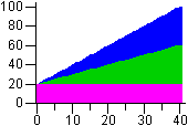 |
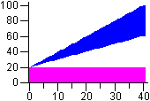 |
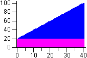 |
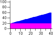 |
| figure 1 | figure 2 | figure 3 | figure 4 |
Assigned axis
Selection of axis that is to be assigned to the object. Assigning an axis is performed by selection of corresponding axis number (from 1 to 99) from Axis number item.
A symbol close to Axis number displays the axis type - A = analogue, D/<figure> = digital/number of level. Level and description on digital axis is not possible to set if some point uses the analogue axis. These data are not necessary then.
Note:
If the object is Boolean type, the digital axis has to be assigned to it. Object values will be drawn
onto the digital axis for which you must select a level (Digital axis level and description
item). Each of defined levels can have a description.
Using the digital axes is described in details in the topic
Axis configuration.
Digital axis level and description
Number and description of the digital axis.
Level
Allows to specify membership to a particular level. Admissible values are in the range 0..50.
This setting is applied when the option displaying in Object levels is selected either in graph configuration
dialog box or in the panel above the graph window. For more information on this topic - see the chapter
"Graph configuration" dialog box.
Drawing
Defines a drawing style relative to zero value on y-axis.
- From X axis - drawing starts from x-axis
- Above 0 - drawing starts from 0 (zero) on Y-axis upward
- Below 0 - drawing starts from 0 (zero) on Y-axis downward
Sensitivity
Sets the sensitivity for point on the graph to display
the values. The value will display with different y-coordinate as the previous
value only if the value change is higher than sensitivity.
For example - the value 0.000589 comes to be drawn in graph. Next value is
0.000587 which will be drawn as change in graph only if the sensitivity is
0.000001, otherwise the line is drawn on the level 0.000589.
Draw till a current time
Some of the flows can contain prepared data to the future, e.g. the predictive flows. The option limits a data drawing up to the current time.
Drop spaces
Causes to leave out the spaces without data in a graph flow.
Related pages:
Pridať komentár