Supported device types and versions
Communication line configuration
Communication station configuration
I/O tag configuration
Literature
Changes and modifications
Document revisions
Protocol supports communication via GPIO (General Purpose I/O) interface on Raspberry PI and computers built on a RPI Compute Module. Currently supported are:
The communication was tested with Raspberry PI (version 3) and NPE-X500-M3-MAX-3G.
The protocol allows reading of digital and analog inputs (in case of NPE-X500 also a value of user button), writing to digital outputs (for NPE-X500 also setting relay outputs, working with user LEDs and a buzzer).
Communication line - configuration dialog box - the Protocol parameter tab.
Parameters defined in the field have effect on some optional protocol parameters. There can be defined the following line protocol parameters:
Table 1
| Full name | Description | Units / size | Default value |
|---|---|---|---|
| Type of device. Currently supported are::
| - | Raspberry PI |
| Name of library with communication functions for a particular device. The used values are:
| - | - |
| Delay after one reading of the values of all I/O tags. Using this parameter, it is possible to control the reading frequency more finely than using the polling parameters in the configuration of time parameters of the station. | ms | 1 |
I/O tag configuration
Possible I/O tag types: Ai, Ao, Ci, Co, Di, Do.
The address format of the I/O tag depends on the device type.
I/O tag addresses for Raspberry PI
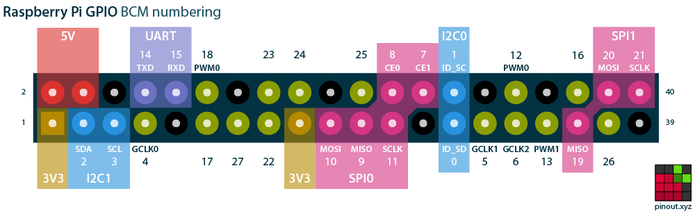
In the following table, id defines the number of ping in BCM (Broadcom) numbering.
Following image copied from http://pinout.xyz shows the BCM pin numbering on the GPIO connector:
Obrázok prevzatý z http://pinout.xyz zobrazuje BCM číslovanie pinov na GPIO konektore
| Adresa | Popis | Typ bodu | Príklady |
|---|---|---|---|
DI,id | GPIO pin bude nakonfigurovaný ako digitálny vstup. Ak bude naň privedené napätie 3.3V, hodnota vstupu bude 1. Ak bude naň privedené napätie 0V (zem), hodnota vstupu bude 0. Varianty DI_UP a DI_DOWN konfigurujú vnútorné pull-up resp. pull-down rezistory, takže na vstup je cez rezistor pripojené napätie (DI_UP) alebo zem (DI_DOWN), takže aj bez pripojenia externého napätia je vstup v definovanom stave. Varianta DI konfiguruje pin tak, že pull-up/pull-down odpory sú odpojené. | Di, Ci, Ai | DI,25 DI_UP,24 |
DO,id | GPIO pin bude nakonfigurovaný ako digitálny výstup. Ak bude doň zapísaná hodnota 1, na výstupe bude napätie 3.3V. Ak bude doň zapísaná hodnota 0, na výstupe bude napätie 0V (zem). | Dout, Co, Ao | DO,24 |
| PWM,id | GPIO pin bude nakonfigurovaný ako PWM (pulse width modulation) výstup. Následne je doň možné zapisovať hodnoty 0-255 riadiace šírku impulzu od úplne vypnutého až po úplne zapnutý. | Dout, Co, Ao | PWM,12 |
| REVISON | Hodnota revízie hardvéru (číslo z riadku "Revision" zo súboru /proc/cpuinfo. Napr. pre RPI 3 je v tomto súbore riadok "Revision : a02082" a hodnota revízie (po prevode z hexadecimálneho tvaru) je 10494082. | Ci | REVISON |
I/O tag addresses for NPE-X500
In the following table, id defines the number of input/output (e.g. DI, DO, AO). The number of inputs and outputs depends on the particular model. The notes are referring to the NPE-X500-M3-MAX-3G that was tested.
Note 1: Output points whose addresses contain _BUF use a buffered writing. This allows the values of such objects not only to be written, but also to be read, which can be useful, for example, after the start of the KOM process.
Note 2: With the tested model, the reading of the digital input took less than 1 ms, while the reading the analog input took approximately 20 ms.
| Address | Description | I/O tag type | Examples |
|---|---|---|---|
DI,id | Digital input (DI) | Di, Ci, Ai | DI,1 DI,2 |
DO,id | Digital output (DO). If buffered (DO_BUFF), the value is also read (during startup and periodically). | Dout, Co, Ao | DO,1 |
| DIO,id DIO_BUF,id | Digital input/output. Based on I/O tag type, the GPIO port is configured as input (Di, Ci, Ai) or output (Dout, Co, Ao). | Input: Di, Ci, Ai Output: Dout, Co, Ao | DIO,2 DIO_BUF,3 |
| RELAY,id RELAY_BUF,id | Relay output. If buffered (RELAY_BUFF), the value is also read (during startup and periodically). | Dout, Co, Ao | RELAY,1 RELAY_BUF,2 |
| AI,id | Analog input (AI). | Ci, Ai | AI,1 |
| LED,id LED_BUF,id | LED output. If buffered (LED_BUFF), the value is also read (during startup and periodically). | Dout, Co, Ao | LED,1 LED_BUF,2 |
| BUZZER BUZZER_BUF | Buzzer. If buffered (BUZZER_BUFF), buzzer status is also read (during startup and periodically). | Dout, Co, Ao | BUZZER BUZZER_BUF |
| BUTTON BUTTON_BUF | User button status. | Di, Ci, Ai | BUTTON |