...
This protocol executes a serial communication with the devices by binary HDLC protocol according to DLMS/COSEM standard. It supports only so-called
Two modes of addressing of I/O tags are supported:
- "Short Name (SN) referencing" using 16-bit object addresses
- "Logical Name (LN) referencing"
...
Devices under test:
...
- using 6-byte OBIS codes
Communication was tested with following devices:
- EMH LZQJ (SN referencing)
- Landis ZMD400 (SN referencing)
- Iskraemec Iskra MT880-M (LN referencing)
Protocol supports time synchronization, the period is configured in station configuration dialog.
| Kotva | ||||
|---|---|---|---|---|
|
...
- Supported line categories: Serial, SerialOverUDP Device Redundant, TCP/IP-TCP, TCP/IP-TCP Redundant, MODEM.MOXA IP Serial Library, MODEM.
| Kotva | ||||
|---|---|---|---|---|
|
...
| Parameter | Meaning | Unit / size | Default value | |||||||||||||
|---|---|---|---|---|---|---|---|---|---|---|---|---|---|---|---|---|
| --- DLMS/HDLC parameters --- | ||||||||||||||||
| Setting of this parameter of DLMS/COSEM protocol. Only ShortShort_Name_Referencing_No_Ciphering context is supported for "Short Name (SN) referencing". | Logical_Name_Referencing_No_Ciphering Short_Name_Referencing_No_Ciphering Logical_Name_Referencing_With_Ciphering Short_Name_Referencing_With_Ciphering | Short_Name_Referencing_No_Ciphering | |||||||||||||
| HDLC MAC address of a client (i.e. D2000 KOM process). A default value is 10H which is the reserved value "Public client". See "DLMS UA 1000-2 Ed. 7.0" document, chapter 8.4.2.3 "Reserved special HDLC addresses". | 0 .. 7FH | 10H | |||||||||||||
| Maximal length of one HDLC frame packet on the receiver from the device. When occurring some communication problems (e.g. checksum error and so on), we recommend you to decrease the value of this parameter. | 250 | ||||||||||||||
| Maximal length of one HDLC frame packet on the transmitter to the device. When occurring some communication problems (e.g. checksum error and so on), we recommend you to decrease the value of this parameter. | 250 | ||||||||||||||
| Maximal length of PDU (data packet). One PDU can be divided into more HDLC frame packets according to settings of HDLC protocol parameters Max_info_field_length-receive parameter and HDLC Max_info_field_length-transmit parameter. Note: a specific electrometer (Landis ZMD.B23 ZMD400) only accepted value of 0, otherwise it returned rejected-permanent error during connection establishment. | 0 .. 65535 | 1200 | |||||||||||||
| A Disconnect request will not be used after the readout of values from a device is finished. During next readout a connection establishment phase is omitted (HDLC mode-setting request and AARQ negotiation request). | YES/NO | NO | of reading values from the device. | YES/NO | NO | ||||||||||
| Device password. If entered, the "Low Level Security" authentication with the entered password is used within the AARQ Association Request. | |||||||||||||||
| Ban of online selection from the list of objects, directly on device, through the DLMS Object List dialog box in configuration of I/O tag address. | YES/NO | NO | |||||||||||||
| Several electrometers implement optimization of time data when reading from profiles (class_id=7). The optimization means that only the first line of data contains a timestamp, others contain null. The time stamp of each row is equal to the previous line's time stamp plus the value of capture_period (4) attribute . If the value of this parameter is YES, the value of the capture_period attribute is read prior to reading the profile data. If the value of this parameter is NO, the content of the capture_period attribute is not read, but the KOM process relies on all profile rows to contain timestamps. If this is not the case, the profile data is not read, and the line logs contain error messages "turn on station parameter 'Profile Data Optimization'". | YES/NO | YES| Kotva | | pas | pas | PasswordDevice password. If entered, the "Low Level Security" authentication with the entered password is used within the AARQ Association Request.||||||||||
| Opening mode of connection with device. If device is configured so that it directly uses DLMS/COSEM protocol on the given interface, set "Direct HDLC". Mostly (e.g. when reading through IR opto interface by optical reading head) you must open the connection by IEC protocol in so-called "mode E" and then transfer to HDLC binary protocol (i.e. DLMS/COSEM). "Mode E", according to specification of IEC protocol, uses the following setting of the transmission parameters:
If "Opening Mode" is set on "IEC mode E", above mentioned transmission parameters must be set. As for Serial communication line, the parameters must be set in the line parameters "Mode 1". See the protocol parameter "Software 7E1". The setting of the baud rate on 300 Baud is not required when using the line of MODEM category. It uses so-called DTE speed, between PC and modem. If this speed is higher than 300 Baud, you have to activate "handshaking" parameter on RTS/CTS in proper line mode. If parameter "Direct HDLC" is set, any dynamic change of transfer parameters is not expected. You can use any Serial line mode and set it by parameter "Line mode" on the station. More information is mentioned in IEC 62056-21, Electricity metering - Data exchange for meter reading, tariff and load control - Part 21: Direct local data exchange, Annex E: "METERING HDLC protocol using protocol mode E for direct local data exchange". See also chapter "Setting of transmission parameters". | Direct HDLC IEC mode E | Direct HDLC | |||||||||||||
| --- IEC Parameters --- | ||||||||||||||||
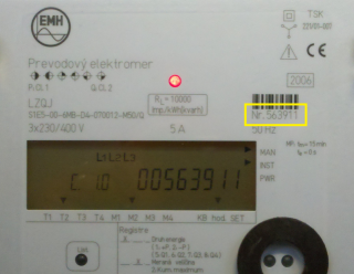
| It is a station address (device) and is used only if Opening mode is set on "IEC Mode E". The parameter is optional. It identifies the address of device at the beginning of communication via IEC protocol. If this parameter is not defined, the address will not be set and the device will always respond. If several devices are connected to one line (e.g. RS485 bus), IEC address of device must be set so that the devices could be identified and avoid a collision. A device address is max. 32 characters consisting of figures (0...9), capital letters (A...Z), small letters (a...z) or blank space ( ). Zeros in front of valid figure are ignored (i.e. address 10203 = 010203 = 000010203). "IEC Device Address" is a serial number of device. This register has address "0-0:C.1.0" - Device ID 1, manufacturing number in OBIS addressing. The picture below shows the front panel of EMH LZQJ device. There is serial number, i.e. IEC address (563911). If device contains a display, this value may be displayed as you can see on the picture.
| - | ||||||||||||||
| This parameter is used only if Opening mode is set on "IEC Mode E". It defines baud rate for the communication through HDLC protocol DLMS/COSEM after changeover from IEC mode E to the HDLC binary communication. As for Serial line, this parameter must set the baud rate on "Mode 2". AUTO option sets the baud rate according to the value from a device. If this baud rate can not be identified, you should trace the diagnostic communication logs. You can find there the following message:
and set the baud rate according to it. HDLC binary communication through DLMS/COSEM protocol unlike the opening IEC step is realized by different parameters which have to be set in "Mode 2" of the Serial line category:
See the parameter "Software 7E1" and the chapter Settings of transmission parameters. | 300 600 1200 2400 4800 9600 19200 AUTO | AUTO | |||||||||||||
| It is used if "Opening mode" is set on "IEC Mode E". YES option switches SW emulation of transfer parameters of 7 data bits, even parity when the transfer parameters of 8 data bits are set, none parity (i.e. emulation 7E1 when 8N1 is set). It enables to use "IEC mode E" option for SerialOverUDP lines that do not support a dynamic changes of transfer parameters. See the chapter Settings of transmission parameters. | YES/NO | NO | |||||||||||||
| It is used if "Opening mode" is set on "IEC Mode E". Nonzero value activates the sending of so-called "wake-up message" which activates the communication interface of battery-powered device. The null characters (0x00) are sent according to quantity that is characterized by the parameter value. The baud rate must be 300 Baud (select "Mode 1" for Serial lines). More information is mentioned in IEC 62056-21, Electricity metering - Data exchange for meter reading, tariff and load control - Part 21: Direct local data exchange, Annex B: "Wake-up methods for battery-operated tariff devices". | 0 .. 120 | 0 | |||||||||||||
| It is used if "Opening mode" is set on "IEC Mode E". If so-called "wake-up" message is activated, this parameter defines a delay after sending of "wake-up" message even before beginning of communication. As for Serial line, we recommend to set "WaitTxEMPTY" parameter in particular line mode. According to the document IEC 62056-21, you should set this parameter on 1,5 up to 1,7 s. | ms | 0 | |||||||||||||
| --- Send/receive parameters --- | ||||||||||||||||
| Delay after sending the request but before reading the response. | ms | 100 ms | |||||||||||||
| Delay between reading the till its completion. | ms | 200 ms | |||||||||||||
| Retry count of reading response till its completion. | 1 .. 100 | 20 | |||||||||||||
| Delay between the request retry if the error communication occurs. | ms | 500 ms | |||||||||||||
| Retry count of request as far as the error communication. | 1 .. 20 | 3 | |||||||||||||
| --- Modem parameters --- | ||||||||||||||||
| Phone number for modem connection with a device (only for MODEM lines). | |||||||||||||||
| Maximum waiting time for dial-up modem connection (only for MODEM lines). | 1 .. 600 s | 60 s | |||||||||||||
| Maximum retry count of dial-up modem connection (only for MODEM lines). | 1 .. 20 | 1 | |||||||||||||
| Delay before attempting to dial after an unsuccessful connection attempt (only for MODEM lines). | 1 .. 600 s | 30 s | |||||||||||||
| Time delay after the dial-up connection has been established (only for MODEM lines) but before the beginning of communication. It is used to stabilize the modem connection mostly as far as the old types of modems. After this timeout passes, all the redundant symbols (the residues of AT modem communication) will be read and ignored. | 0 .. 30 s | 5 s | |||||||||||||
| A special initial string of modem 1 (only for MODEM lines). | AT&FE0V1Q0B0X3L0M0 | ||||||||||||||
| A special initial string of modem 2 (only for MODEM lines). Explanation of recommended settings: S37=5 1200bps DTE-DTE speed - limits the speed for modems. Many devices use modems with limited transfer speeds and this setting can speed-up the connection establishment process. Higher transfer speeds must be negotiated individualy. &D2 DTR drop to hangup - for matching with tha parameter of modem line (line configuration, tab "Modem - parameters", check the option "Use DTR for Hangup"). S0=0 Disable auto-answer. Auto-answer will not be used. S30=2 20 sec inactivity timeout - automatic hangup after idle timeout expired. Necessary for assuring connection termination after the communication with the last device is over.
| termination after the communication with the last device is over.
| ATS37=5&D2S0=0S7=60S30=2 | |||||||||||||
| --- Debug parameters --- | ||||||||||||||||
| This parameter activates debug information from the HDLC protocol level. | YES/NO | NOATS37=5&D2S0=0S7=60S30=2 | |||||||||||||
| Full This parameter activates full communication monitoring. It enables to show display the I/O tag values and other debug information. | YES/NO | NO | |||||||||||||
...
To understand the object addressing in DLMS/COSEM protocol, you should know so-called OBIS standard according to IEC 62056-61 Object Identification system (OBIS), Annex A - Code presentation.
The "Logical Name (LN) referencing" mode uses OBIS addresses of objects.
The supported mode "Short Name (SN) referencing" mode does not use OBIS address but a numerical address in the range of 16 bits.
...
| IEC HDLC setup class_id = 23, version = 1 | |||||
| Attribute | Attribute value type | Attribute description | Support in D2000 | ||
| 1. | logical_name (static) | octet-string (text) | OBIS address of data entity which is represented by an instance of this class. | Yes, separate I/O tag | |
| 2. | comm_speed (static) | enum | Communication speed on the proper port: (0) 300 baud, (1) 600 baud, (2) 1 200 baud, (3) 2 400 baud, (4) 4 800 baud, (5) 9 600 baud, (6) 19 200 baud, (7) 38 400 baud, (8) 5 7 600 baud, (9) 115 200 baud | Yes, separate I/O tag | |
| 3. | window_size_transmit (static) | unsigned | The maximum number of frames that a device or system can transmit before it needs to receive an acknowledgement from a corresponding station. During logon, other values can be negotiated. | Yes, separate I/O tag | |
| 4. | window_size_receive (static) | unsigned | The maximum number of frames that a device or system can receive before it needs to transmit an acknowledgement to the corresponding station. During logon, other values can be negotiated. | Yes, separate I/O tag | |
| 5. | max_info_field_length_transmit (static) | long-unsigned | The maximum information field length that a device can transmit. During logon, a smaller value can be negotiated. | Yes, separate I/O tag | |
| 6. | max_info_field_length_receive (static) | long-unsigned | The maximum information field length that a device can receive. During logon, a smaller value can be negotiated. | Yes, separate I/O tag | |
| 7. | inter_octet_time_out (static) | long-unsigned | Defines the time, expressed in milliseconds, over which, when any character is received from the primary station, the device will treat the already received data as a complete frame. | Yes, separate I/O tag | |
| 8. | inactivity_time_out (static) | long-unsigned | From the primary station, the device will process a disconnection. When this value is set to 0, this means that the inactivity_time_out is not operational. | Yes, separate I/O tag | |
| 9. | device_address (static) | long-unsigned | Contains the physical device address of a device. In the case of one byte addressing: 0x00 NO_STATION Address, 0x01…0x0F Reserved for future use, 0x10...0x7D Usable address space, 0x7E ‘CALLING’ device address, 0x7F Broadcast address In the case of two byte addressing: 0x0000 NO_STATION address, 0x0001..0x000F Reserved for future use, 0x0010..0x3FFD Usable address space, 0x3FFE ‘CALLING’ physical device address, 0x3FFF Broadcast address | Yes, separate I/O tag | |
| Kotva | ||||
|---|---|---|---|---|
|
...
load profiles
The reading of historical data from loading load profiles is made by the instances of COSEM classes "Profile generic" (class_id = 7), i.e. the configuration of I/O tag in attribute 2 ("buffer"). This I/O tag always contains the invalid valued in D2000 System but it enables to read a buffer of the instance of COSEM class "Profile generic".
...
TELL command GETOLDVAL or ESL action GETOLDVAL start the reading of all the configured loading profiles load profiles on the station. The time interval with data is always read by the parameters of TELL command or ESL action from the loading profileload profile.
| Kotva | ||||
|---|---|---|---|---|
|
...
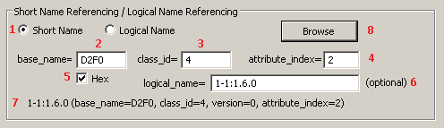
The following picture shows a configuration dialog box of I/O tag address.
Example for Short Name (SN) referencing:
Example for Logical Name (LN) referencing:
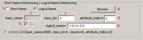

The meaning of the parameters in dialog box:
| 1 | Selection of referencing: Short Name (SN) or Logical Name (LN). Based on the value of the station parameter Application Context the I/O tags with either SN or LN referencing will be handled. | ||
| 2 | SN referencing: required Required parameter, it is the initial address of class instance. It is an integer number within the range 0 up to 65520 (0xFFF0 hexadecimal). LN referencing: unused (disabled) parameter. | ||
| 23 | Required parameter, it is an identification number of COSEM class. | ||
| 34 | Required parameter, it is an index of attribute (a serial number from 1). | ||
| The SN referencing: the parameters base_name, class_id and attribute_index are required mandatory. The parameters base_name and attribute_index are used to calculate Short Name (SN) address according to the formula which helps to get the value of attribute from device. Class_id shows a type of COSEM class. Attribute_index identifies data type that were received from a device. Attribute_index identifies data type that were received from a device. LN referencing: parameters class_id,attribute_index and logical_name are mandatory. | |||
| 5 | SN referencing: the | 4 | The checkbox Hex enables to enter the address base_name in hexadecimal form (checked) or decimal (unchecked). When editing the existing I/O tag, this checkbox is marked depending on the address that was entered in first configuration of I/O tag (i.e. hexadecimal or decimal). The change of status (checked/unchecked) does not convert automatically the value base_name from hexadecimal to decimal and vice-versa. LN referencing: unused (disabled) parameter. |
| 6 | SN referencing: the | 5 | The parameter logical_name is optional. It is OBIS address that belongs to Short Name address, configured by parameters base_name, class_id and attribute_index. It is in a text format according to OBIS specification of object address. load profile. When reading the historical data from the loadingload profile, they are identified by "logical_name" address, i.e. if the address is not entered, the historical data will not be assigned to the existing I/O tag. |
| 76 | In the bottom part, there is information about the object address. Their meaning is only to inform the user about a configured object. The information is initialized after choosing the address in DLMS SN Object list dialog box. | ||
| 78 | Clicking on the button Select in Object list... Browse enables to select the address from DLMS SN Object List dialog box. There are two methods on how to configure the addresses of I/O tags:
| ||
| Kotva | ||||
|---|---|---|---|---|
|
...
Object List dialog box
If these conditions are fulfilled - the device is connected to D2000 System, a communication station exists and the device communicates, you can define the parameters of I/O tag address by the selection of the object from the list of all objects on the device. A List of objects is queried from the device:
- in SN referencing mode: from a special class "Association SN" with predefined address base_name 0xFA00
- in LN referencing mode: from a special class "Association LN" with predefined address logical_name 0.0.40.0.0.255
is intended for reading the list of objects. There is no need to configure any other I/O tags, just click on the button Select in Object list... .button Browse.
First loading of the list takes upto several minutes depending on the baud rate. The window displays the information "Waiting for data...".
After data loading, the list of objects and their description descriptions will show in the window:

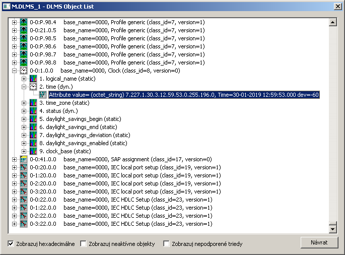
You can find the following information in the list:
- each row represents one instance of COSEM class,
- OBIS address of object follows the icon of class,
- then there is the information about SN address (base_name) of particular instance of COSEM class and about its type (class_id and version),
- when clicking on symbol (+) you can unhide the COSEM classes, which are supported in D2000 SystemD2000 System, can be expanded by clicking on symbol (+).
When opening the main nodexpanding a specific instance of COSEM class, the supported attributes of class will displaybe displayed:

The information about attribute includes:
- attribute index (attribute_index) - means a sequence sequential number of attribute, it follows is displayed next to the icon,
- attribute name (e.g. logical_name, value, scaler_unit, time_zone ...),
- static or dynamic attribute.
There can be next an expand symbol (+) near the icon. When opening it and clicking on the row "Attribute value=", you can get the current value of attribute will be retrieved from the device:

This feature enables fast browsing of the attributes of all supported COSEM classes. The dialog window works as the both "Object List" and "Value Browser".
The bottom part of dialog box contains these checkboxescheck-boxes:
- Show hexadecimal - shows all the addresses of base_name classes as hex number or decimal one.
- Show inactive objects
- Show unsupported classes - enables to display the instances of unsupported COSEM classes.
...
To insert the addressing parameters of attribute of instance into the address of I/O tag, double-click on the particular row. This closes the "DLMS SN Object List" b dialog and the parameters will be set for the I/O tag.
...
- Ver. 1.0 - May 30, 2011 - creation of document.
- Ver. 1.1 - January 30, 2019 - suppor for LN referencing.
| Info | ||
|---|---|---|
| ||
...