...
- EMH LZQJ (SN referencing)
- Landis ZMD400 (SN referencing)
- Iskraemeco Iskra MT880-M (LN referencing)
- ADDAX NP73E.2-18-1 (LN referencing)
- Iskraemeco AC750-G3C2 gateway + Iskraemeco AM550-ED1.11, AM550-TD2.12 electrometers (LN referencing, Gateway mode)
- Iskraemeco AC750-G3C2 gateway + Iskraemeco AM550-ED1.11, AM550-TD2.12 electrometers (LN referencing, Wrapper mode, IPv6 communication)
- Kaifa MA309M (LN referencing, via RS485 or GSM network [TCP port 4059, TCP/UDP Wrapper, Wrapper Source/Destination Port=1], Client MAC Address=1, xDLMS Conformance=3F1F00, Password=00000001)
The protocol supports time synchronization, the period is configured in the station configuration dialog.
...
In ordinary situations, when the physical device is identical with to the logical one (one physical device = one logical device), this address does not need to be changed. If the physical device integrates more logical devices, you should monitor content or "0-0:41.0.0" register of "SAP assignment" class (class_id=17, attribute 2 "SAP_assignment_list") in the "DLMS SN Object List" dialog box. This dialog box shows the list of logical devices that are integrated in into a physical one.

This is the example of a value representation of the "SAP_assignment_list" attribute of the "SAP assignment" class in the device which contains one logical device with Upper MAC Address 16.
See also the protocol parameter "Client MAC address" and a document "DLMS UA 1000-2 Ed. 7.0", chapter 8.4.2.3 "Reserved special HDLC addresses".
Note: for Iskraemec Iskra MT880, Upper MAC Address = 1, Lower MAC Address = 16 + last two digits of the serial number (if, for example, the serial number is 72211943, then Lower MAC Address = 16 + 43 = 59).Kotva NoteIskra NoteIskra
Note: since the station address is DLMS Server HDLC/MAC Address, it is only used when the protocol parameter "Opening mode" is set to "Direct HDLC" or "IEC Mode E" .
| Kotva | |||
|---|---|---|---|
| Kotva | |||
|
...
Communication station configuration dialog box - Protocol parameters tab.
They influences influence some optional protocol parameters. The following station protocol parameters can be set:
...
(Opening Mode) | Opening mode of connection with the device and a used link protocol. If the device is configured so that it directly uses DLMS/COSEM protocol on the given interface, set this parameter to "Direct HDLC". Mostly (e.g. when reading through IR optical interface by an optical reading head) you must open the connection in IEC protocol in so-called "mode E" and then transfer to HDLC binary protocol (i.e. DLMS/COSEM). "IEC mode E", according to the specification of the IEC protocol, uses the following settings of the transmission parameters:
If "Opening Mode" is set to "IEC mode E", the above-mentioned transmission parameters must be set. As for the Serial communication line, the parameters must be set in the line parameters "Mode 1". See the protocol parameter "Software 7E1". The setting of the baud rate to 300 Baud is usually not required when using the line of the MODEM category. A so-called DTE speed is used between a PC and a modem. If this speed is higher than 300 Baud, you have to activate the "handshaking" parameter on RTS/CTS in proper line mode. If the parameter value is set to "Direct HDLC", a dynamic change of transmission parameters is not expected. You can use any Serial line mode and set it by the "Line mode" parameter on the station. More information is mentioned in IEC 62056-21, Electricity metering - Data exchange for meter reading, tariff and load control - Part 21: Direct local data exchange, Annex E: "METERING HDLC protocol using protocol mode E for direct local data exchange". See also the chapter "Setting of transmission parameters". The "UDP Pure" mode is used by some devices when communicating over UDP. Each DLMS/COSEM data packet (challenge/response) is in a separate UDP packet. In the case of TCP, this is problematic (without parsing it is not possible to determine what the size of the DLMS/COSEM data packet is) so the DLMS/COSEM standard defines the use of an envelope - called a Wrapper - for TCP/UDP mode (see next paragraph). The "TCP/UDP Wrapper" mode is used when communicating over TCP or UDP. An 8-byte header (Version, Wrapper Source Port, Wrapper Destination Port, and Length fields) is added to the DLMS/COSEM data.
| Direct HDLC | Direct HDLC | |||||||||||||
| --- DLMS/HDLC parameters --- | ||||||||||||||||
| The setting of the "Application Context" parameter of the DLMS/COSEM protocol. Short_Name_Referencing_No_Ciphering context is supported for "Short Name (SN) referencing". Logical_Name_Referencing_No_Ciphering context is supported for "Logical Name (LN) referencing". The next two contexts with encryption are not supported. | Logical_Name_Referencing_No_Ciphering Short_Name_Referencing_No_Ciphering Logical_Name_Referencing_With_Ciphering Short_Name_Referencing_With_Ciphering | Short_Name_Referencing_No_Ciphering | |||||||||||||
| HDLC MAC address of a client (i.e. D2000 KOM process). The default value is 10H which is the reserved value "Public client".
See "DLMS UA 1000-2 Ed. 7.0" document, chapter 8.4.2.3 "Reserved special HDLC addresses". For the ADDAX NP73E.2-18-1 electricity meter, a different value than 10H had to be configured (1 or 2). For the ISKRA MT880 electricity meter, it was possible to read only a limited set of data (e.g. serial number) with a value of 10H. Active and reactive power could be read as 01H (Client Management Process) or 02H. | 0 .. 7FH | 10H | |||||||||||||
| The maximum length of one HDLC frame packet on the receiver's side. When communication problems occur (e.g. checksum error etc.), we recommend decreasing the value of this parameter. | 250 | ||||||||||||||
| The maximum length of one HDLC frame packet on the transmitter's side. When communication problems occur (e.g. checksum error etc.), we recommend decreasing the value of this parameter. | 250 | ||||||||||||||
| The maximum length of PDU (data packet). One PDU can be divided into more HDLC frame packets according to settings of protocol parameters HDLC Max_info_field_length-receive and HDLC Max_info_field_length-transmit. Note: A specific electricity meter (Landis + Gyr ZMD 400) only accepted a value of 0, otherwise it returned a rejected-permanent error during connection establishment. Another electricity meter (Landis + Gyr ZFD 405) only accepted the value 65535, otherwise it returned a rejected-permanent error during connection establishment. | 0 .. 65535 | 1200 | |||||||||||||
| A Disconnect request will not be used after the readout of values from a device is finished. During the next readout, a connection establishment phase is omitted (HDLC mode-setting request and AARQ negotiation request). | YES/NO | NO | |||||||||||||
| Device password. If entered, the "Low Level Security" authentication with the entered password is used within the AARQ Association Request. | |||||||||||||||
| Online address selection from the list of objects, directly on the device, through the DLMS Object List dialog box in the configuration of the I/O tag address will be disabled. | YES/NO | NO | |||||||||||||
| Several electrometers implement optimization of time data when reading from profiles (class_id=7). The optimization means that only the first row of data contains a timestamp, others contain null. The timestamp of each row is equal to the previous row's timestamp plus the value of the capture_period (4) attribute. If the value of this parameter is YES, the value of the capture_period attribute is read prior to reading the profile data. If the value of this parameter is NO, the content of the capture_period attribute is not read, but the KOM process relies on all profile rows to contain timestamps. If this is not the case, the profile data is not read, and the line logs contain the error messages messages "turn on station parameter 'Profile Data Optimization". | YES/NO | YES | |||||||||||||
| Bit settings in the "xDLMS Conformance" field in the AARQ initial message. The default settings are:
| bits
| /parameterized-access
| 0 | 0 | |||||||||||
| If the value of this parameter is YES, octet-string values will be interpreted as text strings (e.g. "abc") for text I/O tags, otherwise, in binary format, individual octets are separated by a dot (e.g. "97.98.99"). | YES/NO | NO | |||||||||||||
| --- IEC Parameters --- | ||||||||||||||||
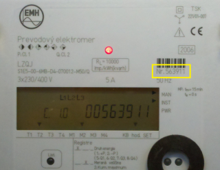
| It is an address of a station (device) and is used only if the Opening mode is set to "IEC Mode E". This parameter is optional. It identifies the address of the device at the beginning of communication via the IEC protocol. If this parameter is not defined, the address will not be set at the communication via the IEC protocol and the device must always respond. If several devices are connected to one line (e.g. RS485 bus), the IEC address of a device must be set so that the devices could can be identified and avoid a collision. A device address is max. 32 characters consisting of figures (0...9), capital letters (A...Z), small letters (a...z), or a blank space ( ). Zeros in front of the valid figure number are ignored (i.e. address 10203 = 010203 = 000010203). "IEC Device Address" is a the serial number of the device. In OBIS addressing, this register has an address "0-0:C.1.0" - Device ID 1, manufacturing number. The picture below shows the front panel of the EMH LZQJ device. There is a serial number, i.e. IEC address (563911). If the device contains a display, this value may be usually displayed as you can see in the picture.
| - | ||||||||||||||
| This parameter is used only if the Opening mode is set to "IEC Mode E". It defines the baud rate for the communication through HDLC protocol DLMS/COSEM after the changeover from IEC mode E to the HDLC binary communication. As for the Serial line, this parameter must set the baud rate to "Mode 2" of the line. AUTO option sets the baud rate according to the value offered by a device. If this baud rate can not be identified, you should check the diagnostic communication logs. The , where the following message can be found there:
and set the baud rate according to it. HDLC binary communication through DLMS/COSEM protocol, unlike the opening IEC step, is realized by different parameters which that have to be set in "Mode 2" of the Serial line category:
See also the "Software 7E1" parameter and the chapter Settings of transmission parameters. | 300 600 1200 2400 4800 9600 19200 AUTO | AUTO | |||||||||||||
| This parameter is used if "Opening mode" is set to "IEC Mode E". Setting it to YES activates an SW emulation of transmission parameters of 7 data bits and even parity when the transmission parameters of 8 data bits and none parity are set (i.e. emulation of 7E1 when 8N1 is set). It enables the use of the "IEC mode E" option for SerialOverUDP lines that do not support dynamic changes of transmission parameters. See the chapter Settings of transmission parameters. | YES/NO | NO | |||||||||||||
| This parameter is used if "Opening mode" is set to "IEC Mode E". Nonzero value activates the sending of a so-called "wake-up message" which activates the communication interface of battery-powered devices. The null characters (0x00) are sent according to the quantity that is defined by the parameter value. The baud rate must be 300 Baud (configured in "Mode 1" for Serial lines). More information is available in IEC 62056-21, Electricity metering - Data exchange for meter reading, tariff and load control - Part 21: Direct local data exchange, Annex B: "Wake-up methods for battery-operated tariff devices". | 0 .. 120 | 0 | |||||||||||||
| This parameter is used if "Opening mode" is set to "IEC Mode E". If a so-called "wake-up" message is activated, this parameter defines a delay after sending a "wake-up" message, before the beginning of communication. In the case of a Serial line, we recommend setting the "WaitTxEMPTY" parameter in a specific line mode. According to document IEC 62056-21, you should set this parameter between 1,5 and 1,7 seconds. | ms | 0 | |||||||||||||
| --- TCP/UDP Wrapper parameters --- | ||||||||||||||||
| This parameter is used if the "Opening mode" protocol parameter is set to "TCP/UDP Wrapper" or "TCP/UDP Wrapper + Gateway protocol". It specifies the value of the Source Port field (2-byte number) in the wrapper header. Reserved ports are according to the standard:
| - | 0 | |||||||||||||
| This parameter is used if the "Opening mode" protocol parameter is set to "TCP/UDP Wrapper" or "TCP/UDP Wrapper + Gateway protocol". It specifies the value of the Destination Port field (2-byte number) in the wrapper header. Reserved ports are according to the standard:
| - | 0 | |||||||||||||
| --- Gateway parameters --- | ||||||||||||||||
| This parameter is used if the "Opening mode" protocol parameter is set to "Gateway protocol" or "TCP/UDP Wrapper + Gateway protocol". It specifies the value of the Device Network ID field in the prefix in the sent request. If only one network exists, value 0 shall be used. | - | 0 | |||||||||||||
| This parameter is used if the "Opening mode" protocol parameter is set to "Gateway protocol" or "TCP/UDP Wrapper + Gateway protocol". It specifies the value of the Device Address field in the prefix in the sent request. | - | - | Note: in the case of the Iskraemeco AC750 gateway, the 8-byte MAC address of the meters on the Power Line Communication bus is used as the Device Address. | - | - | ||||||||||
| --- --- Send/receive parameters --- | ||||||||||||||||
| The delay after sending the request but before reading the response. | ms | 100 ms | |||||||||||||
| The delay between readings of the response until its completion. | ms | 200 ms | |||||||||||||
| A retry count of reading response until its completion. | 1 .. 100 | 20 | |||||||||||||
| The delay between the request retries if a communication error occurs. | ms | 500 ms | |||||||||||||
| A retry count of a request if a communication error occurs. | 1 .. 20 | 3 | |||||||||||||
| --- Modem parameters --- | ||||||||||||||||
| The phone number for modem connection with a device (only for MODEM lines). | |||||||||||||||
| Maximum waiting time for dial-up modem connection (only for MODEM lines). | 1 .. 600 s | 60 s | |||||||||||||
| A maximum retry count of dial-up modem connection (only for MODEM lines). | 1 .. 20 | 1 | |||||||||||||
| Delay before attempting to dial after an unsuccessful connection attempt (only for MODEM lines). | 1 .. 600 s | 30 s | |||||||||||||
| Time delay after the dial-up connection has been established (only for MODEM lines) but before the beginning of communication. It is used to stabilize the modem connection for old types of modems. After this timeout elapses, all the redundant received data (the residues of AT modem communication) will be read and ignored. | 0 .. 30 s | 5 s | |||||||||||||
| A special initial string of modem 1 (only for MODEM lines). | AT&FE0V1Q0B0X3L0M0 | ||||||||||||||
| A special initial string of modem 2 (only for MODEM lines). Explanation of recommended settings: S37=5 1200bps DTE-DTE speed - limits the speed for modems. Many devices use modems with limited transmission speeds and this setting can speed-up the connection establishment process. Higher transmission speeds must be negotiated individually. &D2 DTR drop to hangup - for matching with the parameter of modem line (line configuration, tab "Modem - parameters", check the "Use DTR for Hangup" option). S0=0 Disable auto-answer. Auto-answer will not be used. S30=2 20 sec inactivity timeout - automatic hangup after idle timeout expired. Necessary for assuring to ensure connection termination after the communication with the last device is over. | ATS37=5&D2S0=0S7=60S30=2 | ||||||||||||||
| --- Debug parameters --- | ||||||||||||||||
| This parameter activates debug information from the HDLC protocol level. | YES/NO | NO | |||||||||||||
| This parameter activates full communication monitoring. It enables the displaying of the I/O tag values and other debug information. | YES/NO | NO | |||||||||||||


...
The attributes can be static or dynamic depending on whether their value is static (i.e. unchanging, set by a producer, or in the configuration of the device) or dynamic (changing). In the D2000 System, we recommend configuring only the dynamic attributes, as the value of the measured data entity is in dynamic attributes. If it is necessary for the interpretation of a value in a dynamic attribute (mostly the "value" attribute), other static or dynamic attributes are read automatically. See more information in the section Supported COSEM classes.
...
| Extended register class_id = 4, version = 0 | class with data entity value that is accessible via attribute "value". The multiplication coefficient, which is gained by a static attribute "scaler_unit", is used automatically. A timestamp, which has been gained by the reading of the dynamic attribute "capture_time", is added to the entity value. | ||||
| Attribute | Attribute value type | Attribute description | Support in D2000 | ||
| 1. | logical_name (static) | octet-string (text) | OBIS address of the data entity which is represented by an instance of this class. | Yes, separate I/O tag | |
| 2. | value (dynamic) | CHOICE (see supported types of attribute values) | The value of the data entity. | Yes, the value of an entity | |
| 3. | scaler_unit (static) | - | Technical units and multiply coefficient. | Automatically read | |
| 4. | status (dynamic) | CHOICE (see supported types of attribute values) | Status of the value. The standard does not specify the interpretation of this value. Mostly, it is a numerical value and you can find necessary information about its interpretation in a device manual. | Yes, separate I/O tag | |
| 5. | capture_time (dynamic) | date_time | The timestamp of data entity value. | Automatically read | |
...
| IEC local port setup class_id = 19, version = 1 | Information about the configuration of the communication interface for the communication according to IEC 62056-21. | ||||
| Attribute | Attribute value type | Attribute description | Support in D2000 | ||
| 1. | logical_name (static) | octet-string (text) | OBIS address of data entity which is represented by an instance of this class. | Yes, separate I/O tag | |
| 2. | default_mode(static) | enum | It defines the protocol that is used by a device on a specific port: (0) protocol according to IEC 62056-21 (modes A…E), (1) protocol according to Clause 8 of DLMS UA 1000-2 Ed. 7.0. Using this enumeration value all other attributes of this IC are not applicable, (2) protocol not specified. Using this enumeration value, attribute 4, prop_baud is used for setting the communication speed on the port. All other attributes are not applicable. | Yes, separate I/O tag | |
| 3. | default_baud (static) | enum | Baud rate in so-called "opening sequence": (0) 300 baud, (1) 600 baud, (2) 1 200 baud, (3) 2 400 baud, (4) 4 800 baud, (5) 9 600 baud, (6) 19 200 baud, (7) 38 400 baud, (8) 57 600 baud, (9) 115 200 baud | Yes, separate I/O tag | |
| 4. | prop_baud (static) | enum | Baud rate which is suggested by a device. The values are the same as for "default_baud" attribute above. | Yes, separate I/O tag | |
| 5. | response_time (static) | enum | It defines the minimal time between the receiving of a request (the end of request telegram) and the sending of response (the beginning of response telegram): (0) 20 ms, (1) 200 ms | Yes, separate I/O tag | |
| 6. | device_addr (static) | octet-string | Device address for the IEC 62056-21 protocol. | Yes, separate I/O tag | |
| 7. | pass_p1 (static) | octet-string | Password 1 according to IEC 62056-21. | Yes, separate I/O tag | |
| 8. | pass_p2 (static) | octet-string | Password 2 according to IEC 62056-21. | Yes, separate I/O tag | |
| 9. | pass_w5 (static) | octet-string | Password W5 reserved for national applications. | Yes, separate I/O tag | |
...
| IEC HDLC setup class_id = 23, version = 1 | |||||
| Attribute | Attribute value type | Attribute description | Support in D2000 | ||
| 1. | logical_name (static) | octet-string (text) | OBIS address of the data entity which is represented by an instance of this class. | Yes, separate I/O tag | |
| 2. | comm_speed (static) | enum | Communication speed on a specific port: (0) 300 baud, (1) 600 baud, (2) 1 200 baud, (3) 2 400 baud, (4) 4 800 baud, (5) 9 600 baud, (6) 19 200 baud, (7) 38 400 baud, (8) 5 7 600 baud, (9) 115 200 baud | Yes, separate I/O tag | |
| 3. | window_size_transmit (static) | unsigned | The maximum number of frames that a device or system can transmit before it needs to receive an acknowledgement acknowledgment from a corresponding station. During logon, other values can be negotiated. | Yes, separate I/O tag | |
| 4. | window_size_receive (static) | unsigned | The maximum number of frames that a device or system can receive before it needs to transmit an acknowledgment to the corresponding station. During logon, other values can be negotiated. | Yes, separate I/O tag | |
| 5. | max_info_field_length_transmit (static) | long-unsigned | The maximum information field length that a device can transmit. During logon, a smaller value can be negotiated. | Yes, separate I/O tag | |
| 6. | max_info_field_length_receive (static) | long-unsigned | The maximum information field length that a device can receive. During logon, a smaller value can be negotiated. | Yes, separate I/O tag | |
| 7. | inter_octet_time_out (static) | long-unsigned | Defines the time, expressed in milliseconds, over which, when any character is received from the primary station, the device will treat the already received data as a complete frame. | Yes, separate I/O tag | |
| 8. | inactivity_time_out (static) | long-unsigned | From the primary station, the device will process a disconnection. When this value is set to 0, this means that the inactivity_time_out is not operational. | Yes, separate I/O tag | |
| 9. | device_address (static) | long-unsigned | Contains the physical device address of a device. In the case of one byte addressing: 0x00 NO_STATION Address, 0x01…0x0F Reserved for future use, 0x10...0x7D Usable address space, 0x7E ‘CALLING’ device address, 0x7F Broadcast address In the case of two byte addressing: 0x0000 NO_STATION address, 0x0001..0x000F Reserved for future use, 0x0010..0x3FFD Usable address space, 0x3FFE ‘CALLING’ physical device address, 0x3FFF Broadcast address | Yes, separate I/O tag | |
...
Data about objects that are accessible by the reading of attribute "capture_objects" are stored in the buffer. D2000 System automatically searches for I/O tags that match the objects from the attribute "capture_objects" (by their address parameters). The objects are searched by parameters "logical_name", "class_id", and "attribute_index".
...
For more information see "List of standard OBIS codes and COSEM objects" on http://www.dlms.com, the document "List of standardized OBIS codes, DLMS UA, V2.3, (c) Copyright 1997-2005 DLMS User Association".
...
Frequently listed codes are in the following table:
| OBIS code | Popis |
|---|---|
| Active energy registers: | |
| 1.8.0 | Positive active energy (A+) total [kWh] |
| 1.8.1 | Positive active energy (A+) in tariff T1 [kWh] |
| 1.8.2 | Positive active energy (A+) in tariff T2 [kWh] |
| 1.8.3 | Positive active energy (A+) in tariff T3 [kWh] |
| 1.8.4 | Positive active energy (A+) in tariff T4 [kWh] |
| 2.8.0 | Negative active energy (A+) total [kWh] |
| 2.8.1 | Negative active energy (A+) in tariff T1 [kWh] |
| 2.8.2 | Negative active energy (A+) in tariff T2 [kWh] |
| 2.8.3 | Negative active energy (A+) in tariff T3 [kWh] |
| 2.8.4 | Negative active energy (A+) in tariff T4 [kWh] |
| 15.8.0 | Absolute active energy (A+) total [kWh] |
| 15.8.1 | Absolute active energy (A+) in tariff T1 [kWh] |
| 15.8.2 | Absolute active energy (A+) in tariff T2 [kWh] |
| 15.8.3 | Absolute active energy (A+) in tariff T3 [kWh] |
| 15.8.4 | Absolute active energy (A+) in tariff T4 [kWh] |
| 16.8.0 | Sum active energy without reverse blockade (A+ - A-) total [kWh] |
| 16.8. | Sum active energy without reverse blockade (A+ - A-) in tariff T1 [kWh] |
| 16.8.2 | Sum active energy without reverse blockade (A+ - A-) in tariff T2 [kWh] |
| 16.8.3 | Sum active energy without reverse blockade (A+ - A-) in tariff T3 [kWh] |
| 16.8.4 | Sum active energy without reverse blockade (A+ - A-) in tariff T4 [kWh] |
| 2. Reactive energy registers | |
| 3.8.0 | Positive reactive energy (Q+) total [kvarh] |
| 3.8.1 | Positive reactive energy (Q+) in tariff T1 [kvarh] |
| 3.8.2 | Positive reactive energy (Q+) in tariff T2 [kvarh] |
| 3.8.3 | Positive reactive energy (Q+) in tariff T3 [kvarh] |
| 3.8.4 | Positive reactive energy (Q+) in tariff T4 [kvarh] |
| 4.8.0 | Negative reactive energy (Q-) total [kvarh] |
| 4.8.1 | Negative reactive energy (Q-) in tariff T1 [kvarh] |
| 4.8.2 | Negative reactive energy (Q-) in tariff T2 [kvarh] |
| 4.8.3 | Negative reactive energy (Q-) in tariff T3 [kvarh] |
| 4.8.4 | Negative reactive energy (Q-) in tariff T4 [kvarh] |
| 5.8.0 | Imported inductive reactive energy in 1-st quadrant (Q1) total [kvarh] |
| 5.8.1 | Imported inductive reactive energy in 1-st quadrant (Q1) in tariff T1 [kvarh] |
| 5.8.2 | Imported inductive reactive energy in 1-st quadrant (Q1) in tariff T2 [kvarh] |
| 5.8.3 | Imported inductive reactive energy in 1-st quadrant (Q1) in tariff T3 [kvarh] |
| 5.8.4 | Imported inductive reactive energy in 1-st quadrant (Q1) in tariff T4 [kvarh] |
| 6.8.0 | Imported capacitive reactive energy in 2-nd quadrant (Q2) total [kvarh] |
| 6.8.1 | Imported capacitive reactive energy in 2-nd quadr. (Q2) in tariff T1 [kvarh] |
| 6.8.2 | Imported capacitive reactive energy in 2-nd quadr. (Q2) in tariff T2 [kvarh] |
| 6.8.3 | Imported capacitive reactive energy in 2-nd quadr. (Q2) in tariff T3 [kvarh] |
| 6.8.4 | Imported capacitive reactive energy in 2-nd quadr. (Q2) in tariff T4 [kvarh] |
| 7.8.0 | Exported inductive reactive energy in 3-rd quadrant (Q3) total [kvarh] |
| 7.8.1 | Exported inductive reactive energy in 3-rd quadrant (Q3) in tariff T1 [kvarh] |
| 7.8.2 | Exported inductive reactive energy in 3-rd quadrant (Q3) in tariff T2 [kvarh] |
| 7.8.3 | Exported inductive reactive energy in 3-rd quadrant (Q3) in tariff T3 [kvarh] |
| 7.8.4 | Exported inductive reactive energy in 3-rd quadrant (Q3) in tariff T4 [kvarh] |
| 8.8.0 | Exported capacitive reactive energy in 4-th quadrant (Q4) total [kvarh] |
| 8.8.1 | Exported capacitive reactive energy in 4-th quadr. (Q4) in tariff T1 [kvarh] |
| 8.8.2 | Exported capacitive reactive energy in 4-th quadr. (Q4) in tariff T2 [kvarh] |
| 8.8.3 | Exported capacitive reactive energy in 4-th quadr. (Q4) in tariff T3 [kvarh] |
| 8.8.4 | Exported capacitive reactive energy in 4-th quadr. (Q4) in tariff T4 [kvarh] |
| 3. Apparent energy registers | |
| 9.8.0 | Apparent energy (S+) total [kVAh] |
| 9.8.1 | Apparent energy (S+) in tariff T1 [kVAh] |
| 9.8.2 | Apparent energy (S+) in tariff T2 [kVAh] |
| 9.8.3 | Apparent energy (S+) in tariff T3 [kVAh] |
| 9.8.4 | Apparent energy (S+) in tariff T4 [kVAh] |
| 4. Registers of active energy per phases | |
| 21.8.0 | Positive active energy (A+) in phase L1 total [kWh] |
| 41.8.0 | Positive active energy (A+) in phase L2 total [kWh] |
| 61.8.0 | Positive active energy (A+) in phase L3 total [kWh] |
| 22.8.0 | Negative active energy (A-) in phase L1 total [kWh] |
| 42.8.0 | Negative active energy (A-) in phase L2 total [kWh] |
| 62.8.0 | Negative active energy (A-) in phase L3 total [kWh] |
| 35.8.0 | Absolute active energy (|A|) in phase L1 total [kWh] |
| 55.8.0 | Absolute active energy (|A|) in phase L2 total [kWh] |
| 75.8.0 | Absolute active energy (|A|) in phase L3 total [kWh] |
| 5. Maximum demand registers: | |
| 1.6.0 | Positive active maximum demand (A+) total [kW] |
| 1.6.1 | Positive active maximum demand (A+) in tariff T1 [kW] |
| 1.6.2 | Positive active maximum demand (A+) in tariff T2 [kW] |
| 1.6.3 | Positive active maximum demand (A+) in tariff T3 [kW] |
| 1.6.4 | Positive active maximum demand (A+) in tariff T4 [kW] |
| 2.6.0 | Negative active maximum demand (A-) total [kW] |
| 2.6.1 | Negative active maximum demand (A-) in tariff T1 [kW] |
| 2.6.2 | Negative active maximum demand (A-) in tariff T2 [kW] |
| 2.6.3 | Negative active maximum demand (A-) in tariff T3 [kW] |
| 2.6.4 | Negative active maximum demand (A-) in tariff T4 [kW] |
| 15.6.0 | Absolute active maximum demand (|A|) total [kW] |
| 15.6.1 | Absolute active maximum demand (|A|) in tariff T1 [kW] |
| 15.6.2 | Absolute active maximum demand (|A|) in tariff T2 [kW] |
| 15.6.3 | Absolute active maximum demand (|A|) in tariff T3 [kW] |
| 15.6.4 | Absolute active maximum demand (|A|) in tariff T4 [kW] |
| 3.6.0 | Positive reactive maximum demand (Q+) total [kvar] |
| 4.6.0 | Negative reactive maximum demand (Q-) total [kvar] |
| 5.6.0 | Reactive maximum demand in Q1 (Q1) total [kvar] |
| 6.6.0 | Reactive maximum demand in Q2 (Q2) total [kvar] |
| 7.6.0 | Reactive maximum demand in Q3 (Q3) total [kvar] |
| 8.6.0 | Reactive maximum demand in Q4 (Q4) total [kvar] |
| 9.6.0 | Apparent maximum demand (S+) total [kVA] |
| 6. Cumulative maximum demand registers | |
| 1.2.0 | Positive active cumulative maximum demand (A+) total [kW] |
| 1.2.1 | Positive active cumulative maximum demand (A+) in tariff T1 [kW] |
| 1.2.2 | Positive active cumulative maximum demand (A+) in tariff T2 [kW] |
| 1.2.3 | Positive active cumulative maximum demand (A+) in tariff T3 [kW] |
| 1.2.4 | Positive active cumulative maximum demand (A+) in tariff T4 [kW] |
| 2.2.0 | Negative active cumulative maximum demand (A-) total [kW] |
| 2.2.1 | Negative active cumulative maximum demand (A-) in tariff T1 [kW] |
| 2.2.2 | Negative active cumulative maximum demand (A-) in tariff T2 [kW] |
| 2.2.3 | Negative active cumulative maximum demand (A-) in tariff T3 [kW] |
| 2.2.4 | Negative active cumulative maximum demand (A-) in tariff T4 [kW] |
| 15.2.0 | Absolute active cumulative maximum demand (|A|) total [kW] |
| 15.2.1 | Absolute active cumulative maximum demand (|A|) in tariff T1 [kW] |
| 15.2.2 | Absolute active cumulative maximum demand (|A|) in tariff T2 [kW] |
| 15.2.3 | Absolute active cumulative maximum demand (|A|) in tariff T3 [kW] |
| 15.2.4 | Absolute active cumulative maximum demand (|A|) in tariff T4 [kW] |
| 3.2.0 | Positive reactive cumulative maximum demand (Q+) total [kvar] |
| 4.2.0 | Negative reactive cumulative maximum demand (Q-) total [kvar] |
| 5.2.0 | Reactive cumulative maximum demand in Q1 (Q1) total [kvar] |
| 6.2.0 | Reactive cumulative maximum demand in Q2 (Q2) total [kvar] |
| 7.2.0 | Reactive cumulative maximum demand in Q3 (Q3) total [kvar] |
| 8.2.0 | Reactive cumulative maximum demand in Q4 (Q4) total [kvar] |
| 9.2.0 | Apparent cumulative maximum demand (S+) total [kVA] |
| 7. Demands in a current demand period | |
| 1.4.0 | Positive active demand in a current demand period (A+) [kW] |
| 2.4.0 | Negative active demand in a current demand period (A-) [kW] |
| 15.4.0 | Absolute active demand in a current demand period (|A|) [kW] |
| 3.4.0 | Positive reactive demand in a current demand period (Q+) [kvar] |
| 4.4.0 | Negative reactive demand in a current demand period (Q-) [kvar] |
| 5.4.0 | Reactive demand in a current demand period in Q1 (Q1) [kvar] |
| 6.4.0 | Reactive demand in a current demand period in Q2 (Q2) [kvar] |
| 7.4.0 | Reactive demand in a current demand period in Q3 (Q3) [kvar] |
| 8.4.0 | Reactive demand in a current demand period in Q4 (Q4) [kvar] |
| 9.4.0 | Apparent demand in a current demand period (S+) [kVA] |
| 8. Demands in the last completed demand period | |
| 1.5.0 | Positive active demand in the last completed demand period (A+) [kW] |
| 2.5.0 | Negative active demand in the last completed demand period (A-) [kW] |
| 15.5.0 | Absolute active demand in the last completed demand period (|A|) [kW] |
| 3.5.0 | Positive reactive demand in the last completed demand period (Q+) [kvar] |
| 4.5.0 | Negative reactive demand in the last completed demand period (Q-) [kvar] |
| 5.5.0 | Reactive demand in the last completed demand period in Q1 (Q1) [kvar] |
| 6.5.0 | Reactive demand in the last completed demand period in Q2 (Q2) [kvar] |
| 7.5.0 | Reactive demand in the last completed demand period in Q3 (Q3) [kvar] |
| 8.5.0 | Reactive demand in the last completed demand period in Q4 (Q4) [kvar] |
| 9.5.0 | Apparent demand in the last completed demand period (S+) [kVA] |
| 9. Instantaneous power registers | |
| 1.7.0 | Positive active instantaneous power (A+) [kW] |
| 21.7.0 | Positive active instantaneous power (A+) in phase L1 [kW] |
| 41.7.0 | Positive active instantaneous power (A+) in phase L2 [kW] |
| 61.7.0 | Positive active instantaneous power (A+) in phase L3 [kW] |
| 2.7.0 | Negative active instantaneous power (A-) [kW] |
| 22.7.0 | Negative active instantaneous power (A-) in phase L1 [kW] |
| 42.7.0 | Negative active instantaneous power (A-) in phase L2 [kW] |
| 62.7.0 | Negative active instantaneous power (A-) in phase L3 [kW] |
| 15.7.0 | Absolute active instantaneous power (|A|) [kW] |
| 35.7.0 | Absolute active instantaneous power (|A|) in phase L1 [kW] |
| 55.7.0 | Absolute active instantaneous power (|A|) in phase L2 [kW] |
| 75.7.0 | Absolute active instantaneous power (|A|) in phase L3 [kW] |
| 16.7.0 | Sum active instantaneous power (A+ - A-) [kW] |
| 36.7.0 | Sum active instantaneous power (A+ - A-) in phase L1 [kW] |
| 56.7.0 | Sum active instantaneous power (A+ - A-) in phase L2 [kW] |
| 76.7.0 | Sum active instantaneous power (A+ - A-) in phase L3 [kW] |
| 3.7.0 | Positive reactive instantaneous power (Q+) [kvar] |
| 23.7.0 | Positive reactive instantaneous power (Q+) in phase L1 [kvar] |
| 43.7.0 | Positive reactive instantaneous power (Q+) in phase L2 [kvar] |
| 63.7.0 | Positive reactive instantaneous power (Q+) in phase L3 [kvar] |
| 4.7.0 | Negative reactive instantaneous power (Q-) [kvar] |
| 24.7.0 | Negative reactive instantaneous power (Q-) in phase L1 [kvar] |
| 44.7.0 | Negative reactive instantaneous power (Q-) in phase L2 [kvar] |
| 64.7.0 | Negative reactive instantaneous power (Q-) in phase L3 [kvar] |
| 9.7.0 | Apparent instantaneous power (S+) [kVA] |
| 29.7.0 | Apparent instantaneous power (S+) in phase L1 [kVA] |
| 49.7.0 | Apparent instantaneous power (S+) in phase L2 [kVA] |
| 69.7.0 | Apparent instantaneous power (S+) in phase L3 [kVA] |
| 10. Electricity network quality registers | |
| 11.7.0 | Instantaneous current (I) [A] |
| 31.7.0 | Instantaneous current (I) in phase L1 [A] |
| 51.7.0 | Instantaneous current (I) in phase L2 [A] |
| 71.7.0 | Instantaneous current (I) in phase L3 [A] |
| 91.7.0 | Instantaneous current (I) in neutral [A] |
| 11.6.0 | Maximum current (I max) [A] |
| 31.6.0 | Maximum current (I max) in phase L1 [A] |
| 51.6.0 | Maximum current (I max) in phase L2 [A] |
| 71.6.0 | Maximum current (I max) in phase L3 [A] |
| 91.6.0 | Maximum current (I max) in neutral [A] |
| 12.7.0 | Instantaneous voltage (U) [V] |
| 32.7.0 | Instantaneous voltage (U) in phase L1 [V] |
| 52.7.0 | Instantaneous voltage (U) in phase L2 [V] |
| 72.7.0 | Instantaneous voltage (U) in phase L3 [V] |
| 13.7.0 | Instantaneous power factor |
| 33.7.0 | Instantaneous power factor in phase L1 |
| 53.7.0 | Instantaneous power factor in phase L2 |
| 73.7.0 | Instantaneous power factor in phase L3 |
| 14.7.0 | Frequency [Hz] |
| 11. Tamper registers (energy registers and registers of elapsed time) | |
| C.53.1 | Tamper 1 energy register |
| C.53.2 | Tamper 2 energy register |
| C.53.3 | Tamper 3 energy register |
| C.53.4 | Tamper 4 energy register |
| C.53.11 | Tamper 5 energy register |
| C.53.5 | Tamper 1 time counter register |
| C.53.6 | Tamper 2 time counter register |
| C.53.7 | Tamper 3 time counter register |
| C.53.9 | Tamper 4 time counter register |
| C.53.10 | Tamper 5 time counter register |
| 12. Events registers (counters and time-stamps) | |
| C.2.0 | Event parameters change - counter |
| C.2.1 | Event parameters change - timestamp |
| C.51.1 | Event terminal cover opened - counter |
| C.51.2 | Event terminal cover opened - timestamp |
| C.51.3 | Event main cover opened - counter |
| C.51.4 | Event main cover opened - timestamp |
| C.51.5 | Event magnetic field detection start - counter |
| C.51.6 | Event magnetic field detection start - timestamp |
| C.51.7 | Event reverse power flow - counter |
| C.51.8 | Event reverse power flow - timestamp |
| C.7.0 | Event power down - counter |
| C.7.10 | Event power down - timestamp |
| C.51.13 | Event power up - counter |
| C.51.14 | Event power up – timestamp |
| C.51.15 | Event RTC (Real Time Clock) set - counter |
| C.51.16 | Event RTC (Real Time Clock) set - timestamp |
| C.51.21 | Event terminal cover closed - counter |
| C.51.22 | Event terminal cover closed - timestamp |
| C.51.23 | Event main cover closed - counter |
| C.51.24 | Event main cover closed - timestamp |
| C.51.25 | Event log-book 1 erased - counter |
| C.51.26 | Event log-book 1 erased - timestamp |
| C.51.27 | Event fraud start - counter |
| C.51.28 | Event fraud start - timestamp |
| C.51.29 | Event fraud stop - counter |
| C.51.30 | Event fraud stop - timestamp |
| 13. Miscellaneous registers used in sequences | |
| 0.9.1 | Current time (hh:mm:ss) |
| 0.9.2 | Date (YY.MM.DD or DD.MM.YY) |
| 0.9.4 | Date and Time (YYMMDDhhmmss) |
| 0.8.0 | Demand period [min] |
| 0.8.4 | Load profile period [min] (option) |
| 0.0.0 | Device address 1 |
| 0.0.1 | Device address 2 |
| 0.1.0 | MD reset counter |
| 0.1.2 | MD reset timestamp |
| 0.2.0 | Firmware version |
| 0.2.2 | Tariff program ID |
| C.1.0 | Meter serial number |
| C.1.2 | Parameters file code |
| C.1.4 | Parameters check sum |
| C.1.5 | Firmware built date |
| C.1.6 | Firmware check sum |
| C.6.0 | Power down time counter |
| C.6.1 | Battery remaining capacity |
| F.F.0 | Fatal error meter status |
| C.87.0 | Active tariff |
| 0.2.1 | Parameters scheme ID |
| C.60.9 | Fraud flag |
| 0.3.0 | Active energy meter constant |
| 0.4.2 | Current transformer ratio |
| 0.4.3 | Voltage transformer ratio |
| Kotva | ||||
|---|---|---|---|---|
|
...
- DLMS User Association, COSEM Architecture and Protocols, Seventh Edition, (c) Copyright 1997-2009 DLMS User Association (Green book).
- DLMS User Association, COSEM Identification System and Interface Classes, Ed. 10.0, (c) Copyright 1997-
- DLMS User Association, COSEM Architecture and Protocols, Seventh Edition, (c) Copyright 1997-2009 DLMS User Association (Green book).
- DLMS User Association, COSEM Identification System and Interface Classes, Ed. 10.0, (c) Copyright 1997-2010 DLMS User Association (Blue book).
- International Standard IEC 62056-21, Direct Data Local Exchange, First edition 2002-05.-05.
- International Standard IEC 62056-42, Physical layer services and procedures for connection-oriented asynchronous data exchange
- International Standard IEC 62056-46, Data link layer using HDLC protocol
- International Standard IEC 62056-61, Object Identification System (OBIS), Second edition 2006-11.
- List of standardized OBIS codes, DLMS UA, V2.3, (c) Copyright 1997-2005 DLMS User Association.
...
| Info | ||
|---|---|---|
| ||
You can read blogs about the DLMS protocol (for now, in Slovak language only): : |
| Info | ||||||
|---|---|---|---|---|---|---|
| ||||||
The attached ZIP contains the configuration of the line, station, and I/O tags for communication with the Iskra electricity meter. Active and reactive power (-P, -P) are read every few seconds.
|
| Kotva | ||||
|---|---|---|---|---|
|
...
- Ver. 1.0 - May 30, 2011 - Document created.
- Ver. 1.1 - January 30, 2019 - Support for LN referencing.
- Ver. 1.2 - November 11, 2021 - Support for TCP/UDP Wrapper and Gateway protocol.
| Info | ||
|---|---|---|
| ||
...